Face-lifting device

a facelifting and chin technology, applied in the field of facelifting devices, can solve the problems of inability to follow or maintain the plane, difficulty in “feeling” the fibrous plane, and the risk of affecting the smoothness of the undercutting, so as to minimize the amount of tissue that has to be removed, quick and accurate facelifting or tightening maneuvers

Inactive Publication Date: 2005-12-13
WEBER PAUL J
View PDF52 Cites 455 Cited by
  • Summary
  • Abstract
  • Description
  • Claims
  • Application Information

AI Technical Summary

Benefits of technology

[0017]It is an object of the present invention is to provide a method and a device that can be used by surgeons to pro

Problems solved by technology

Planes between the soft internal organs are usually loose and spongy.
Sharp instrument undermining is usually performed to separate highly fibrous or collagenous tissues; however, sharp undermining suffers from the risk of penetrating adjacent tissues inadvertently because of loss of ability to follow the desired plane.
Inability to follow or maintain the plane in sharp undermining is frequently due to limited visibility, difficulty “feeling” the fibrous plane, or scarring (collagen fibrosis) resulting from previous trauma or surgery.
Even experienced surgeons may from time to time lose the correct plane of sharp undermining; great skill is required.
Unfortunately, blunt undermining between highly fibrous tissues such as the human face usually causes tunneling with thick fibrous walls.
Trauma to these nerves can cause a permanent facial deformity or palsy.
If a surgeon were to move, shove, or forwardly-push a blunt, dull-tipped, 1-inch chisel or pencil shaped device through the fat of the face where SQ abuts the dermis, the sheer thickness of the fiber bundles would likely cause slippage of the device and result in the formation of pockets or tunnels surrounded by compacted fiber bundles or septae.
Disadvantages of the current techniques are numerous.
Inadvertent lateral cutting or tissue trauma may be difficult to control.
In addition, speed of separation is important to reduce the time that the patient is exposed to anesthetic drugs; time duration of anesthesia may be directly related to the risk of anesthetic complications.
Use of prior art undermining devices (including scissors, sharp rhytisectors, etc.) in these planes during cosmetic surgery has, at times, resulted in unwanted cutting, trauma or perforation of adjacent structures.
Unfortunately, scissors with 3 dimensionally “bulbous”, rounded tips cannot close all the way to cut target tissue.
Scissors with 2 dimensionally rounded tips can close all the way to cut target tissue but may wander inadvertently between tissue planes due to the thin third dimension (thickness) of the scissors blades.
Current face-lifting instruments that cut with other than manual energy do not address

Method used


Image

  • Face-lifting device
  • Face-lifting device
  • Face-lifting device

Examples


Embodiment Construction

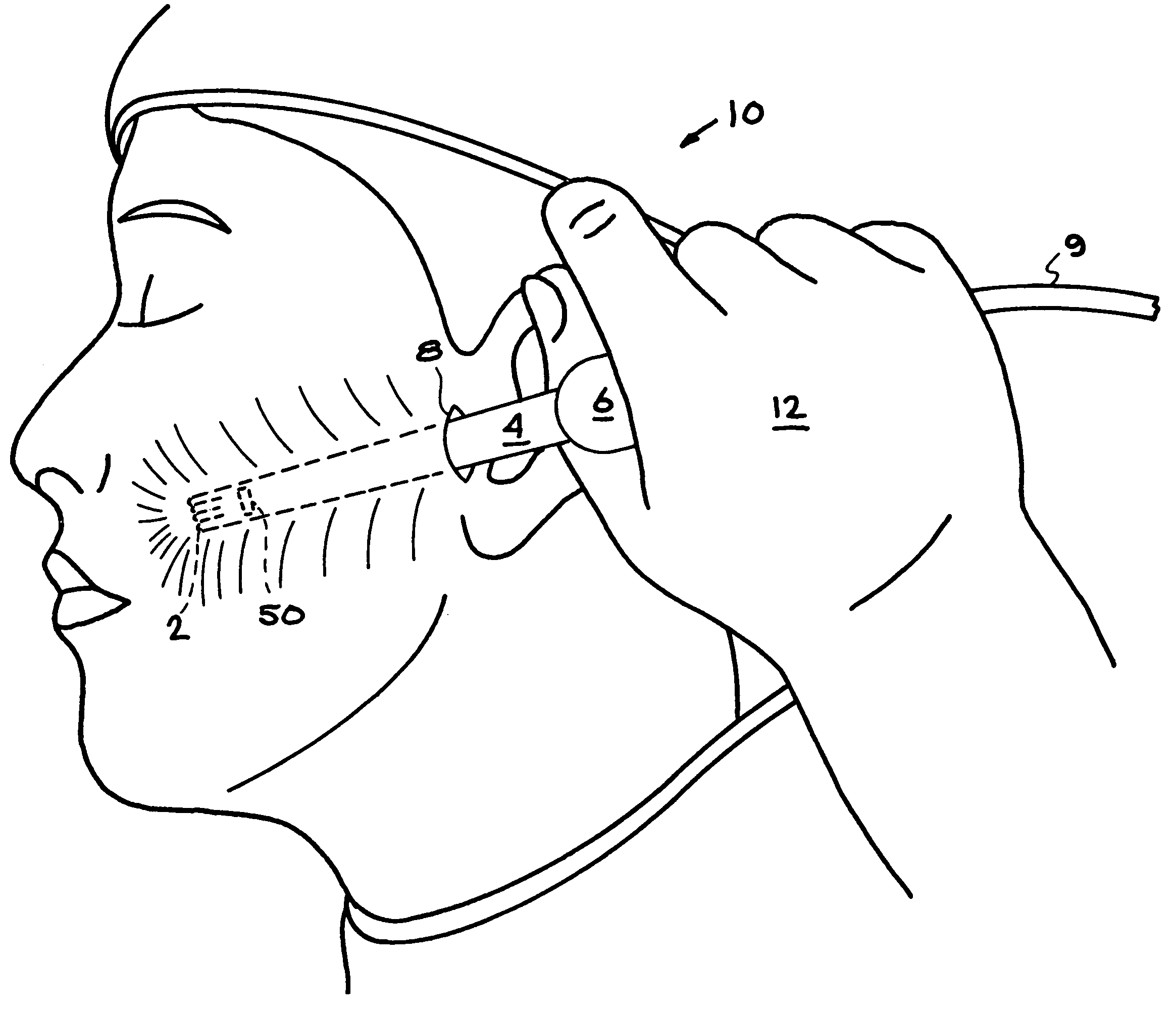
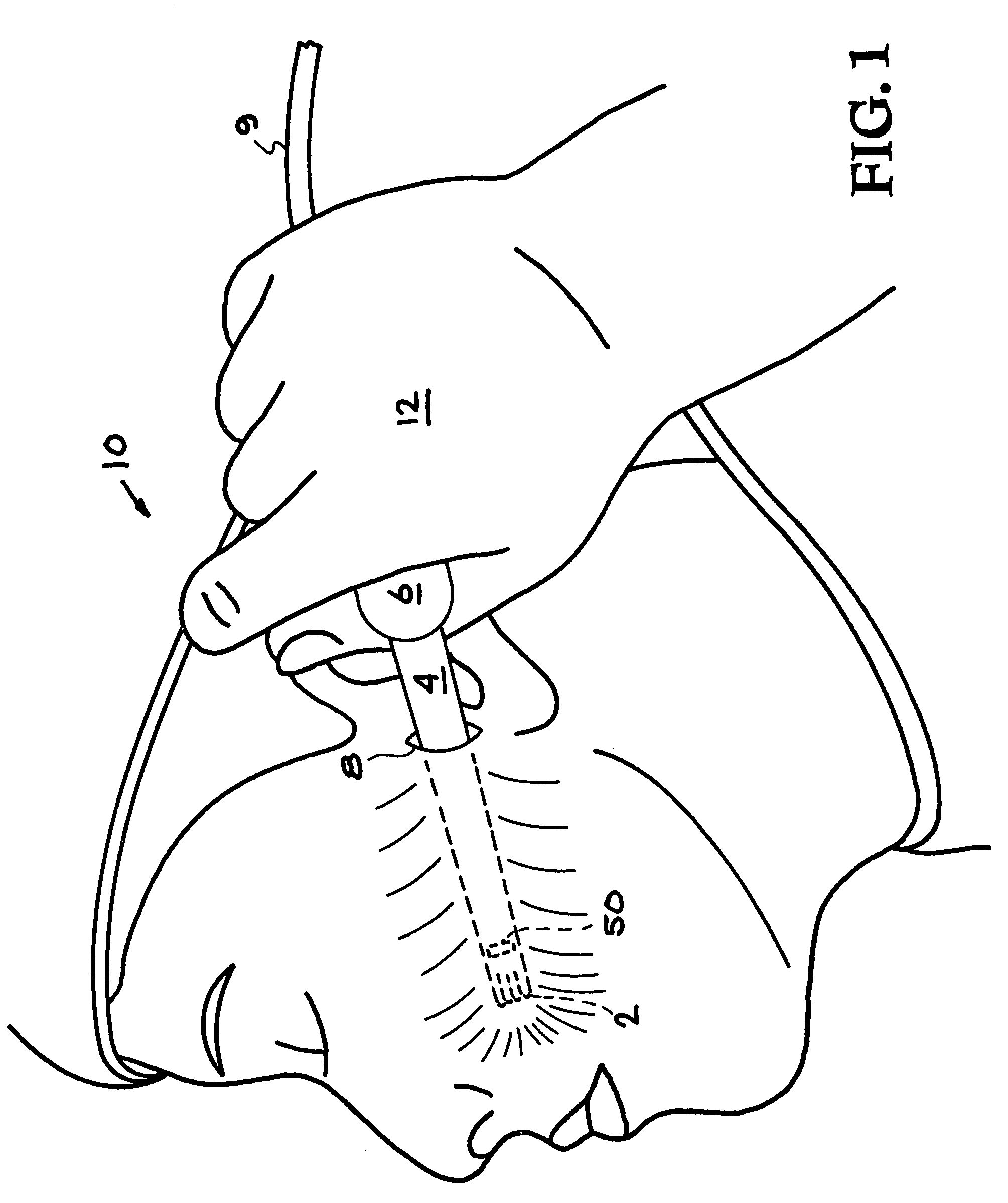
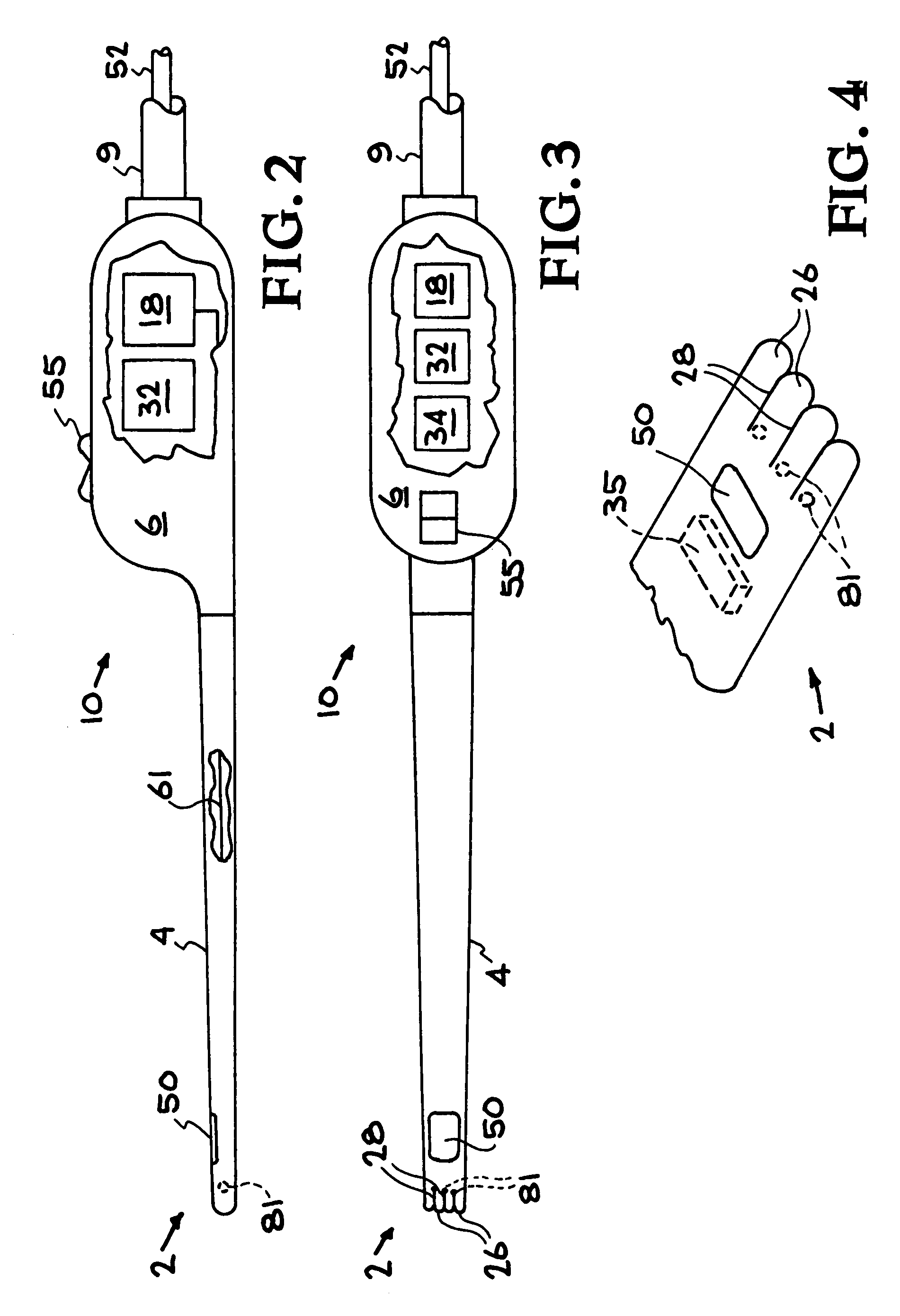
[0080]The present invention provides a device that can be used by surgeons to provide quick and accurate face-lifting maneuvers that minimize the amount of tissue that has to be removed. The device is comprised of a hollow undermining shaft that can be easily positioned between dissection planes in tissue and then manipulated to separate tissue planes and lyse fibrous tissue. A laser light source and delivering means delivers energy to the distal end of the shaft. Embodiments of the invention provide a planar application of energy. A temperature sensor monitors the tissue temperature, and control electronics process temperature information to control the laser power for optimum tissue contraction. An optional secondary light source that is visible to the surgeon can be used to help visualize the location of the laser exit window. Optionally the device can also use ultrasound energy delivered down the shaft to improve tissue lysing.

[0081]Laser-Energized Embodiment

[0082]FIG. 1 shows a...


PUM


Abstract

A device is described that can be used by surgeons to provide quick and accurate face-lifting maneuvers that minimize the amount of tissue that has to be removed. The device is comprised of a shaft with a relatively planar but possibly lenticulate and even slightly curved tip that can divide and energize various tissue planes causing contraction especially via the fibrous tissues. Various forms of energy can be delivered down the shaft to heat and cause desirable tissue contraction. The device can also include a temperature sensor that can be used to control power output.

Description

[0001]This application is a continuation-in-part of U.S. patent application Ser. No. 09 / 475,635, now U.S. Pat. No. 6,440,121, titled “Surgical Device For Performing Face-Lifting Surgery Using Radio Frequency Energy”, filed Dec. 30, 1999 and U.S. patent application Ser. No. 09 / 478,172, now U.S. Pat. No. 6,432,101, titled “Surgical Device For Performing Face-lifting Surgery Using Electromagnetic Radiation”, filed Jan. 5, 2000 and U.S. patent application Ser. No. 09 / 588,436, now U.S. Pat. No. 6,391,023, titled “Thermal Radiation Facelift Device”, filed Jun. 6, 2000, all incorporated herein by reference.BACKGROUND OF THE INVENTION[0002]1. Field of the Invention[0003]The invention relates to face-lifting devices, and more specifically, it relates to a surgical device for performing face-lifting while altering the tissue planes on the undersurface of the face using various forms of energy.[0004]2. Description of Related Art[0005]Definitions, Critical Anatomy and Nomenclature:[0006]Cutting...

Claims


Application Information

Patent Timeline
IPC IPC(8): A61B17/00A45D44/22A61B18/00A61B18/08A61B18/12A61B18/14A61B18/18A61B18/20A61B18/22A61N7/02
CPCA61B18/1402A61B18/08A61B18/201A61B18/203A61B2017/00084A61B2017/0046A61B2017/00761A61B2017/00792A61B2017/00853A61B2018/00017A61B2018/00452A61B2018/1807A61B2018/2272A61N7/022A61N2007/0008
Inventor WEBER, PAUL J.DA SILVA, LUIZ B.RUBENCHIK, ALEXANDER M.
Owner WEBER PAUL J
Why Eureka
Try Eureka