Multiple-sided intraluminal medical device

a medical device and multi-sided technology, applied in the field of medical devices, can solve problems such as compounded problems, and achieve the effect of reducing stress and fatigu

Inactive Publication Date: 2005-12-13
COOK MEDICAL TECH LLC
View PDF55 Cites 401 Cited by
  • Summary
  • Abstract
  • Description
  • Claims
  • Application Information

AI Technical Summary

Benefits of technology

[0006]The foregoing problems are solved and a technical advance is achieved in an illustrative multiple-sided intraluminal medical device comprised of a single piece of wire or other material having a plurality of sides and bends interconnecting adjacent sides. The bends can be coils, fillets, or other configurations to reduce stress and fatigue. The single piece of wire is preferably joined by an attachment mechanism, such as a piece of cannula and solder, to form a closed circumference frame. The device has a first configuration wherein the sides and bends generally lie within a single, flat plane. In an embodiment having four equal sides, the frame is folded into a second configuration where opposite bends are brought in closer proximity to one another toward one end of the device, while the other opposite ends are folded in closer proximity together toward the opposite end of the device. In the second configuration, the device becomes a self-expanding stent. In a third configuration, the device is compressed into a delivery device, such as a catheter, such that the sides are generally beside one another. While the preferred embodiment is four-sided, other polygonal shapes can be used as well.
[0007]In another aspect of the present invention, one or more barbs can be attached to the frame for anchoring the device in the lumen of a vessel. The barbs can be extensions of the single piece of wire or other material comprising the frame, or they can represent a second piece of material that is separately attached to the frame by a separat

Problems solved by technology

The challenge is designing a device that can be delivered to the target vessel in as small of a configuration as possible, while still being capa

Method used


Image

  • Multiple-sided intraluminal medical device
  • Multiple-sided intraluminal medical device
  • Multiple-sided intraluminal medical device

Examples


second embodiment

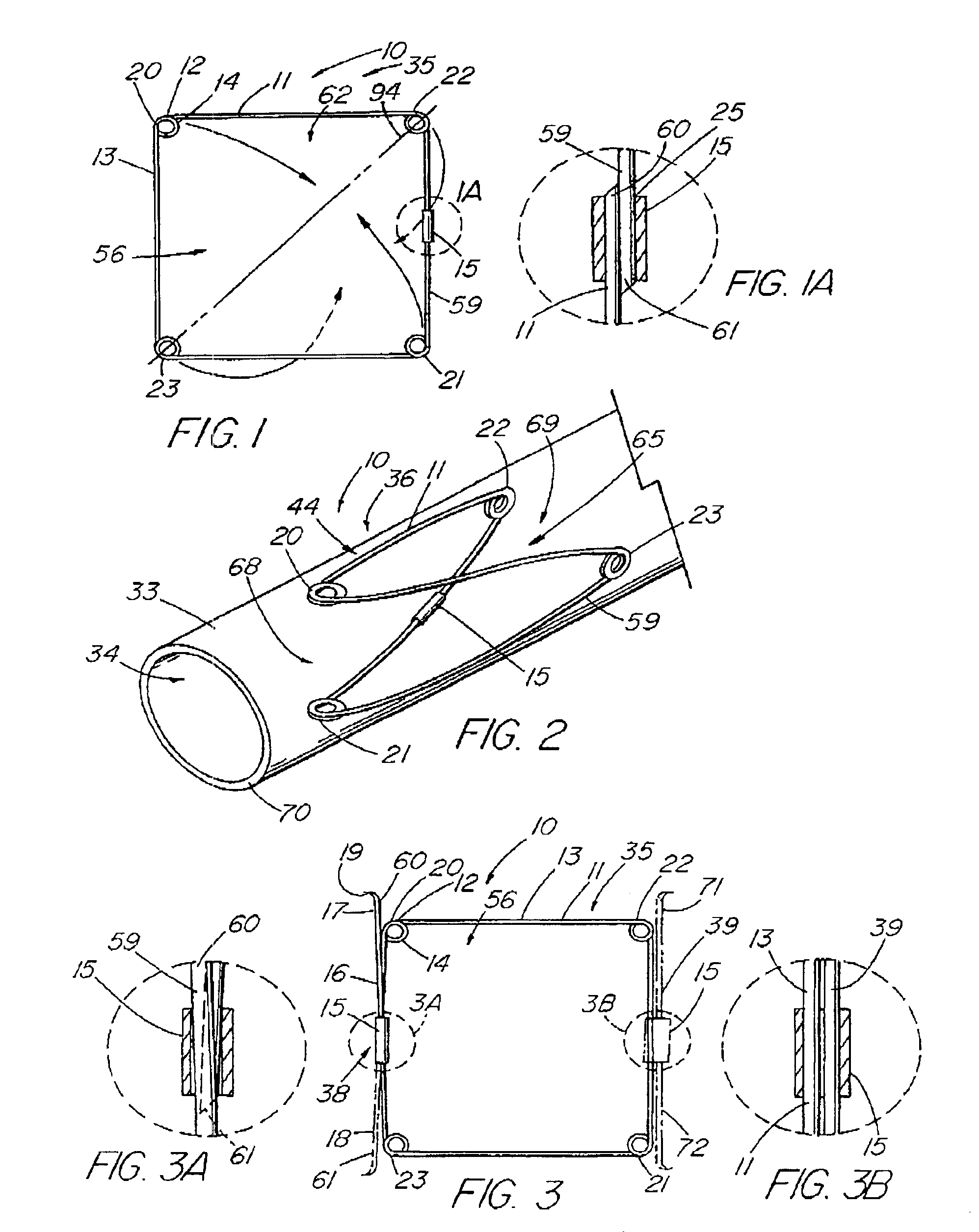
[0031]the present invention is depicted in FIG. 3 wherein one or more barbs 19 are included to anchor the device 10 following deployment. As understood, a barb can be a wire, hook, or any structure attached to the frame and so configured as to be able to anchor the device 10 within a lumen. The illustrative embodiment includes a first strut 17 with up to three other barbed struts 18,71,72, indicated in dashed lines, representing alternative embodiments. As depicted in detail view FIG. 3A, in the combination 38 that comprises struts 17 and 18, each strut is an extension of the single piece 59 of material of the frame 11 beyond the closed circumference 59. The attachment cannula 15 secures and closes the single piece 59 of material into the frame 11 as previously described, while the first and second ends 60,61 thereof, extend from the cannula 15, running generally parallel with the side 13 of the frame 11 from which they extend, each preferably terminating around or slightly beyond r...

third embodiment

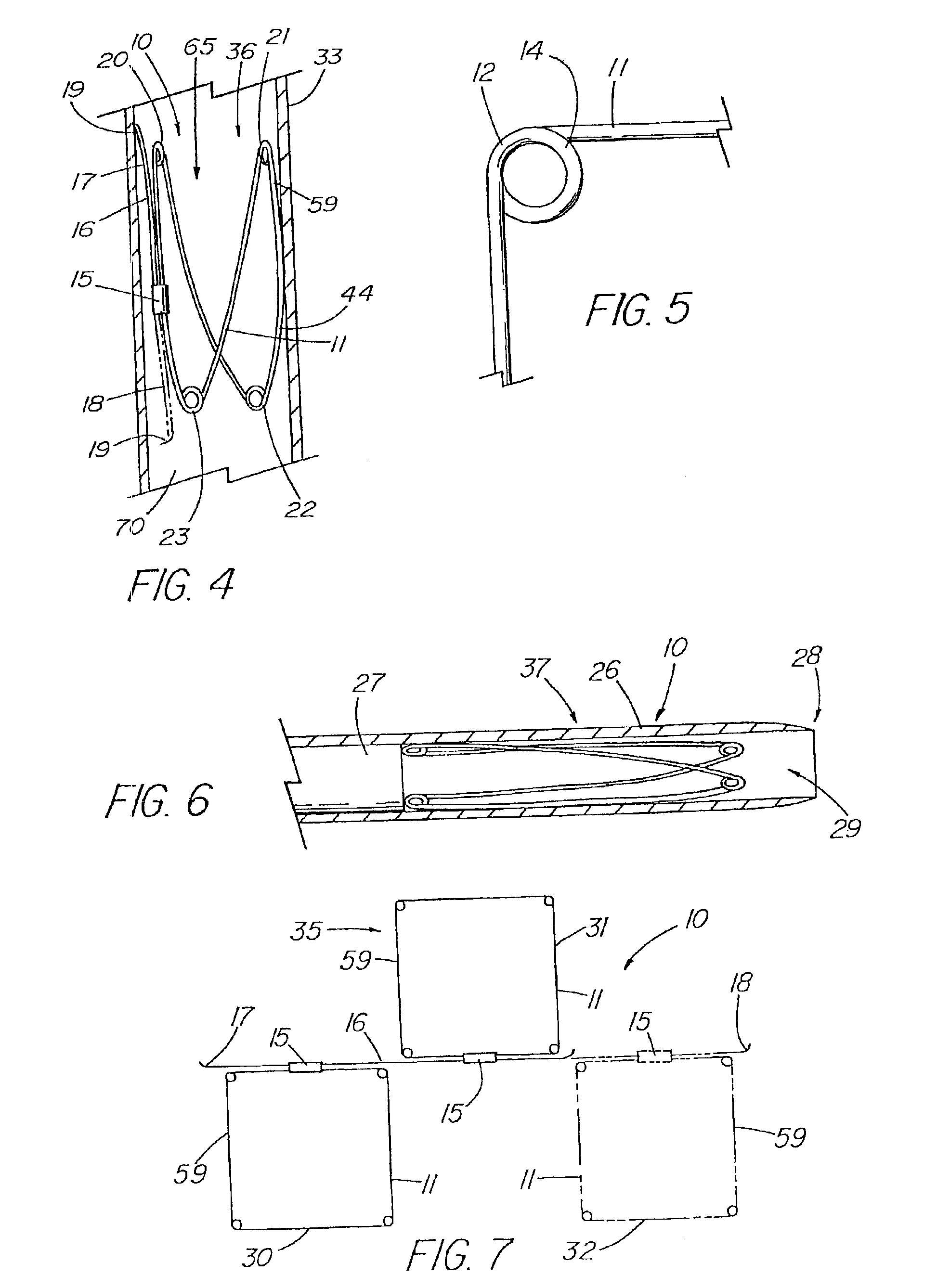
[0033]FIG. 7 depicts a top view of the present invention in the first configuration 35 that includes a plurality of frames 11 attached in series. In the illustrative embodiment, a first frame 30 and second frame 31 are attached by a strut 16 that is secured to each frame by their respective attachment mechanisms 15. The strut 16 can be a double-barbed strut 39 as shown in FIG. 3 (and detail view FIG. 3B) that is separate from the single pieces 59 comprising frames 30 and 31, or the strut may represent a long extended end of the one of the single pieces 59 as shown in detail view FIG. 3A. Further frames, such as third frame 32 shown in dashed lines, can be added by merely extending the length of the strut 16. FIG. 8 depicts a side view of the embodiment of FIG. 7 in the second configuration 36 as deployed in a vessel 33.

[0034]FIGS. 12-18 depict embodiments of the present invention in which a covering 45 comprising a sheet of fabric, collagen (such as small intestinal submucosa), or o...

fourth embodiment

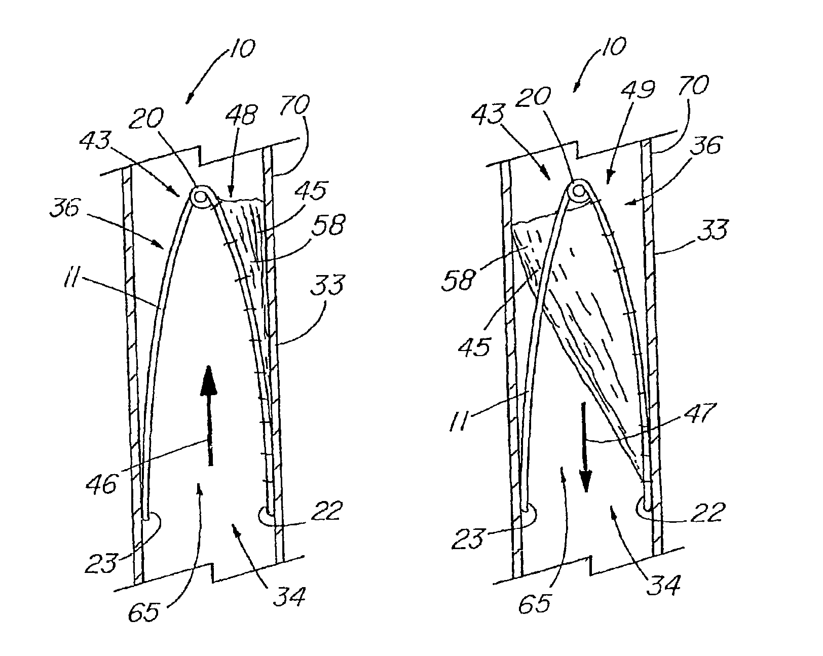
[0035]depicts a top view of the present invention while in the first configuration 35, in which the covering 45 is a partial covering 58, triangular in shape, that extends over approximately half of the aperture 56 of the frame 11. When formed into the second configuration 36 as shown in FIGS. 13-14, the device 10 can act as an artificial valve 43 such as the type used to correct valvular incompetence. FIG. 13 depicts the valve 43 in the open configuration 48. In this state, the partial covering 58 has been displaced toward the vessel wall 70 due to positive fluid pressure, e.g., normal venous blood flow 46, thereby opening a passageway 65 through the frame 11 and the lumen 34 of the vessel 33. As the muscles relax, producing retrograde blood flow 47, as shown in FIG. 14, the partial covering 58 acts as a normal valve by catching the backward flowing blood and closing the lumen 34 of the vessel. In the case of the artificial valve 43, the partial covering 58 is forced against the ve...


PUM


Abstract

A multiple-sided medical device comprises a closed frame of a single piece of wire or other resilient material and having a series of bends and interconnecting sides. The device has both a flat configuration and a second, folded configuration that comprises a self-expanding stent. The stent is pushed from a delivery catheter into the lumen of a duct or vessel. One or more barbs are attached to the frame of the device for anchoring or to connect additional frames. A covering of fabric or other flexible material such as DACRON, PTFE, or collagen, is sutured or attached to the frame to form an occlusion device, a stent graft, or an artificial valve such as for correcting incompetent veins in the lower legs and feet. A partial, triangular-shaped covering over the lumen of the device allows the valve to open with normal blood flow and close to retrograde flow.

Description

CROSS-REFERENCE TO RELATED APPLICATIONS[0001]This is a continuation application of U.S. patent application Ser. No. 09 / 804,128, filed Mar. 12, 2001, now U.S. Pat. No. 6,508,833 which is a continuation of U.S. patent application Ser. No. 09 / 324,382 filed Jun. 2, 1999, now U.S. Pat. No. 6,200,336 B1, which claimed priority from U.S. Provisional patent application Ser. No. 60 / 087,661 filed Jun. 2, 1998.TECHNICAL FIELD[0002]This invention relates to medical devices, more particularly, to intraluminal devices.BACKGROUND OF THE INVENTION[0003]As minimally invasive techniques and instruments for placement of intraluminal devices have developed over recent years, the number and types of treatment devices have proliferated as well. Stents, stent grafts, occlusion devices, artificial valves, shunts, etc., have provided successful treatment for a number of conditions that heretofore required surgery or lacked an adequate solution altogether. Minimally invasive intravascular devices have especi...

Claims


Application Information

Patent Timeline
IPC IPC(8): A61F2/86A61F2/07A61F2/24
CPCA61F2/07A61F2/2475A61F2/86A61F2002/075A61F2002/8483A61F2002/8486A61F2/848A61F2/89A61F2220/005A61F2220/0058A61F2230/005A61F2230/0095A61F2220/0008A61F2220/0016A61F2220/0075A61F2230/0008A61M29/00
Inventor PAVCNIK, DUSANKELLER, FREDERICK S.ROSCH, JOSEFOSBORNE, THOMAS A.
Owner COOK MEDICAL TECH LLC
Why Eureka
Try Eureka