Apparatus and method for controlling the voltage applied to an electrostatic shield used in a plasma generator

a technology of electrostatic shield and apparatus, which is applied in the direction of fluid pressure measurement, semiconductor/solid-state device testing/measurement, instruments, etc., can solve the problems of contaminant production, high cost, and high cost, and achieves simple control, small interaction, and high cost

Inactive Publication Date: 2005-12-13
LAM RES CORP
View PDF16 Cites 13 Cited by
  • Summary
  • Abstract
  • Description
  • Claims
  • Application Information

AI Technical Summary

Benefits of technology

[0007]An alternative powering scheme uses an external second auxiliary RF power supply separate from the main supply that powers the coil as illustrated in FIG. 2. The advantages of this scheme are the option to operate the shield at a different frequency from the antenna, the substantially smaller interaction between the shield and the coil circuit, and simplicity of control. However such extra circuitry results in higher cost and may complicate control.

Problems solved by technology

As a result, problems arise in that contaminants are produced in the process chamber and the dielectric wall is worn off quickly.
However, the current that is coupled out of the coil reduces the magnetic coupling with the plasma.
Although such a powering scheme is simple and efficient, the controls of recipe variables are therefore limited.
However such extra circuitry results in higher cost and may complicate control.

Method used


Image

  • Apparatus and method for controlling the voltage applied to an electrostatic shield used in a plasma generator
  • Apparatus and method for controlling the voltage applied to an electrostatic shield used in a plasma generator
  • Apparatus and method for controlling the voltage applied to an electrostatic shield used in a plasma generator

Examples


Embodiment Construction

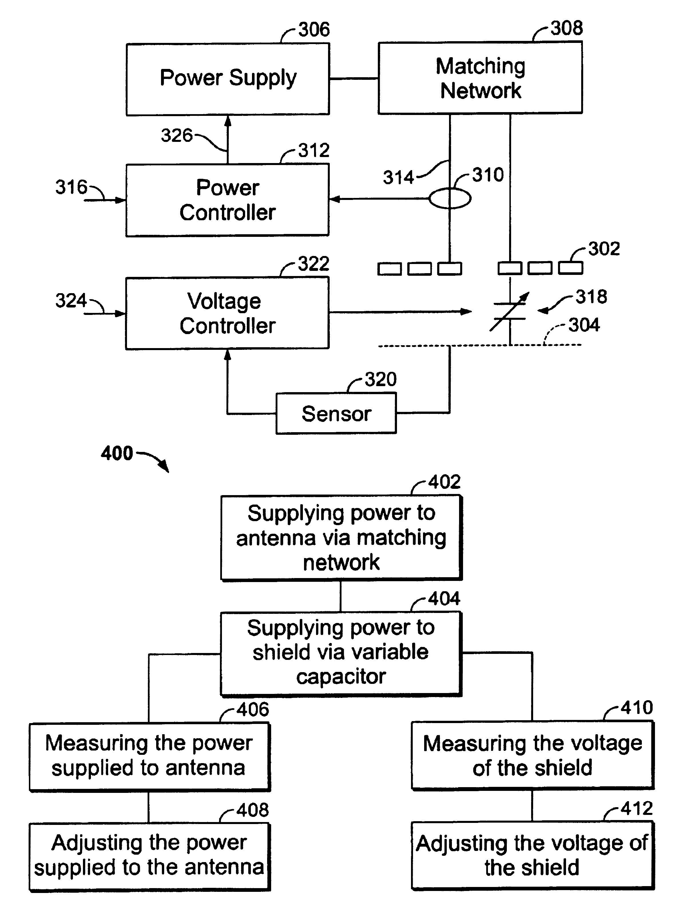
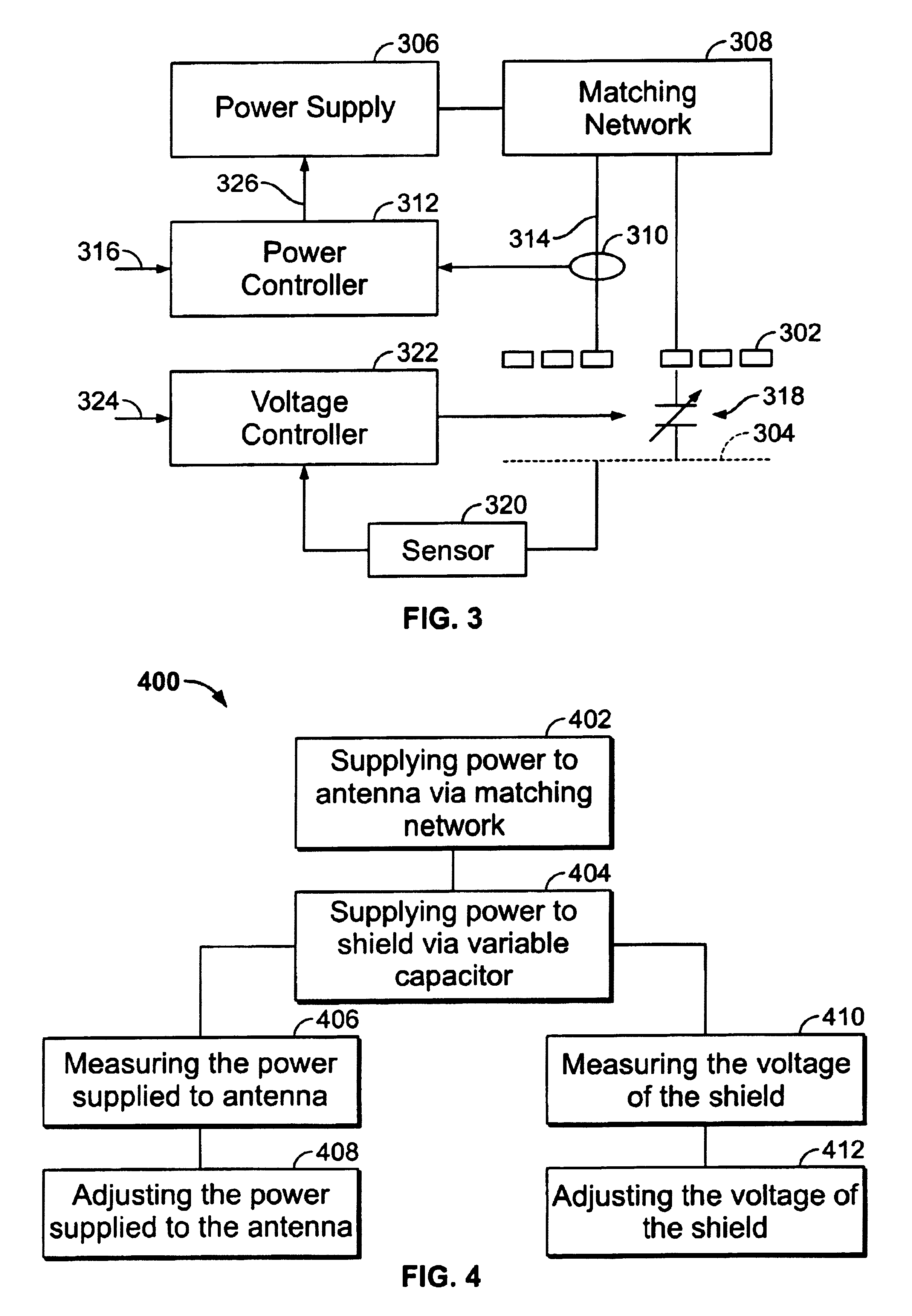
[0018]Embodiments of the present invention are described herein in the context of an apparatus and method for controlling the voltage applied to an electrostatic shield disposed between an induction coil and the plasma it is used to generate. Those of ordinary skill in the art will realize that the following detailed description of the present invention is illustrative only and is not intended to be in any way limiting. Other embodiments of the present invention will readily suggest themselves to such skilled persons having the benefit of this disclosure. Reference will now be made in detail to implementations of the present invention as illustrated in the accompanying drawings. The same reference indicators will be used throughout the drawings and the following detailed description to refer to the same or like parts.

[0019]In the interest of clarity, not all of the routine features of the implementations described herein are shown and described. It will, of course, be appreciated th...


PUM

PropertyMeasurementUnit
frequencyaaaaaaaaaa
frequencyaaaaaaaaaa
voltageaaaaaaaaaa

Abstract

An apparatus for controlling the voltage applied to a shield interposed between an induction coil powered by a power supply via a matching network, and the plasma it generates, comprises a shield, a first feedback circuit, and a second feedback circuit. The power supply powers the shield. The first feedback circuit is connected to the induction coil for controlling the power supply. The second feedback circuit is connected to the shield for controlling the voltage of the shield. Both first and second feedback circuits operate at different frequency ranges. The first feedback circuit further comprises a first controller and a first sensor. The first sensor sends a first signal representing the power supplied to the inductive coil to the first controller. The first controller adjusts the power supply such that the power supplied to the inductor coil is controlled by a first set point. The second feedback circuit further comprises a second sensor, a second controller, and a variable impedance network. The shield is powered via a variable impedance network. The second sensor sends a second signal representative of the voltage of the shield to the second controller. The second controller adjusts the variable impedance network such that the voltage of the shield is controlled by a second set point.

Description

CROSS-REFERENCE TO RELATED APPLICATIONS[0001]The application is a divisional of U.S. patent application Ser. No. 09 / 834,523, filed on Apr. 12, 2001 now U.S. Pat. No. 6,592,710 and commonly owned herewith. U.S. patent application Ser. No. 09 / 834,523 is, in turn, a continuation-in-part of U.S. patent application Se. No. 09 / 676,462, filed on Sep. 29, 2000 now U.S. Pat. No. 6,422,173, which is in turn, a continuation-in-part of U.S. application Ser. No. 09 / 608,883, filed on Jun. 30, 2000 now U.S. Pat. No. 6,531,030, both commonly assigned.FIELD OF THE INVENTION[0002]The present invention relates to a plasma processing apparatus. More particularly, the present invention relates to a method and apparatus for controlling the voltage applied to an electrostatic shield disposed between an induction coil and a plasma.BACKGROUND OF THE INVENTION[0003]Inductively coupled type dry etching systems are commonly used in the semiconductor manufacturing industry. The dry etching apparatus generally h...

Claims


Application Information

Patent Timeline
Patent Type & Authority Patents(United States)
IPC IPC(8): H05H1/46H01J37/32H01L21/3065
CPCH01J37/321H01J37/32697H01J37/32935H01J37/3299H01J37/32
Inventor BENJAMIN, NEILKUTHI, ANDRAS
Owner LAM RES CORP
Why Eureka
Try Eureka