
Method and system for a generation of a two-level signal

a modulation signal and two-level technology, applied in the field of modulation system and to a modulated signal generation method, can solve the problems of limited efficiency, non-linearity of extremely amplitude, heat and/or operation time problems in the transmitter equipment, etc., and achieve high linearity, high power efficiency, and high efficiency

Inactive Publication Date: 2005-12-13
NOKIA CORP
View PDF5 Cites 66 Cited by
  • Summary
  • Abstract
  • Description
  • Claims
  • Application Information

AI Technical Summary

Benefits of technology

[0014]It is an advantage of the invention that it provides a single constant envelope signal in the form of a two-level signal, which can be amplified using a single nonlinear amplifier, e.g. a switching mode amplifier. Thereby, the non-coherent power combining of the traditional LINC system can be avoided.
[0015]It is further an advantage of the invention that it provides an alternative to a Sigma-Delta modulator.
[0016]The constant envelope modulators of the proposed modulation system can be either digital constant envelope modulators or analog constant envelope modulators. Digital constant envelope modulators modulate the transition times of pulse trains going through. The input signals to the combining portion are in this case pulse position modulated (PPM) signals, whereas the output signal of the combining portion is a PWM signal. Analog constant envelope modulators modulate the phase of a sinusoidal carrier depending on a received control signal. The invention has the advantage over the known delta-signal modulation in that the width of the resulting pulses is not discrete, discrete pulse widths causing quantization noise.
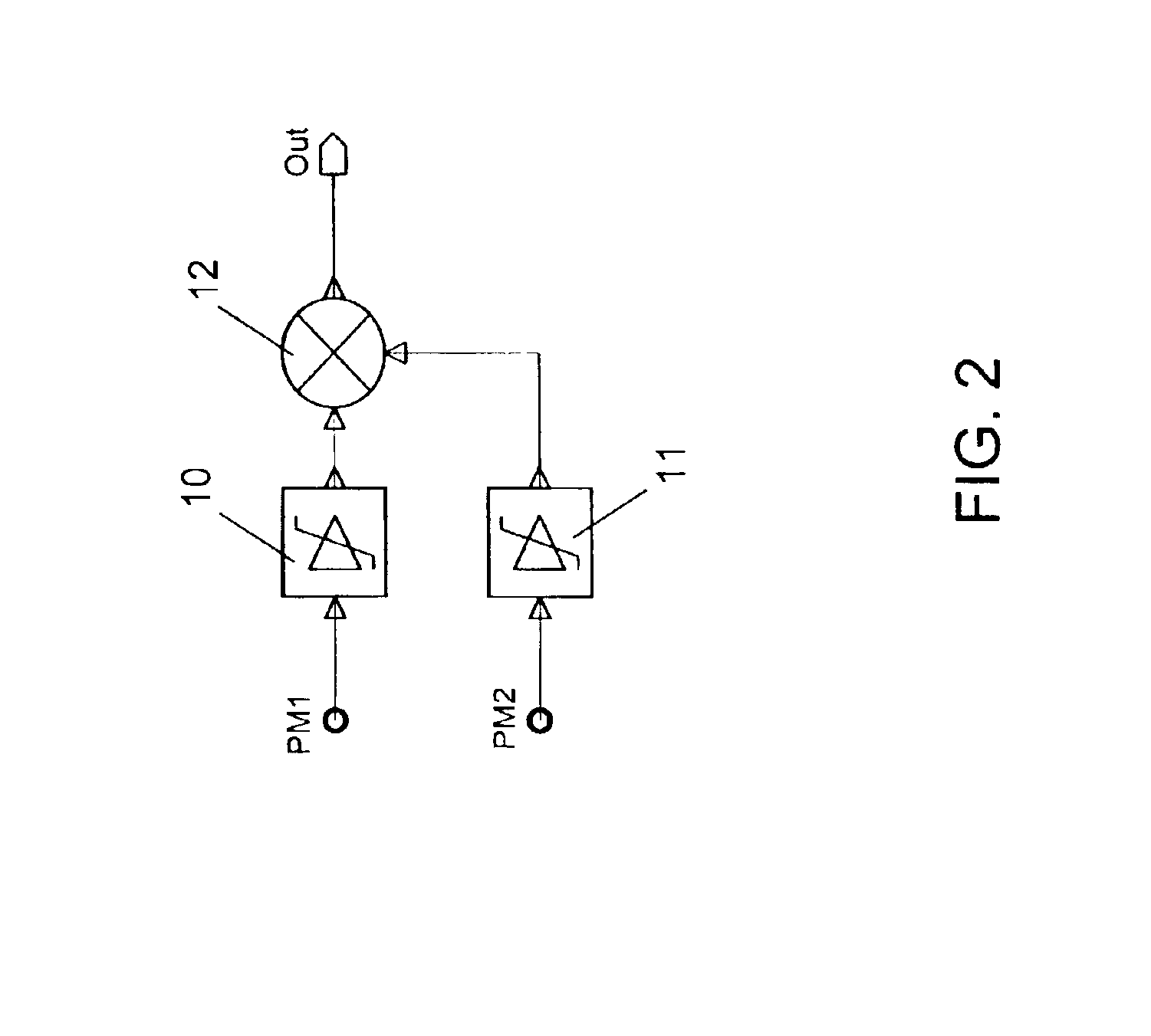
[0017]The single two-level constant envelope signal which is generated in accordance with the invention can be provided in particular, though not exclusively, to a switching mode amplifier for amplification. If the single two-level constant envelope signal is fed to a switching mode amplifier, both high linearity and high power efficiency can be achieved in the amplification.
[0018]Known switching mode amplifiers are for instance class D or class E amplifiers. Class-E amplifiers, which are suitable for radio frequencies, do not work well with varying duty cycle of a provided signal, though. Class-D power amplifiers are inherently well suited for signal with varying duty cycles. Further, it has been presented by H. Kobayashi, J. Hinrichs and P. M. Asbeck in: “Current mode Class-D Power Amplifiers for High Efficiency RF Applications”, IEEE MTT-S 2001 International Microwave Symposium Digest, pp. 939-942, that class D power amplifiers can also work at radio frequencies.

Problems solved by technology

With variable envelope modulation methods, however, the limited efficiency of conventional power amplifiers may cause heat and / or operation time problems in the transmitter equipment, in particular in thermally limited equipment like terminals.
They have the disadvantage that they are extremely amplitude non-linear, but they do not alter significantly the phase of the input phase modulated signals.
A problem of this system is the combination of two non-coherent amplified signals.

Method used


Image

  • Method and system for a generation of a two-level signal
  • Method and system for a generation of a two-level signal
  • Method and system for a generation of a two-level signal

Examples


Embodiment Construction

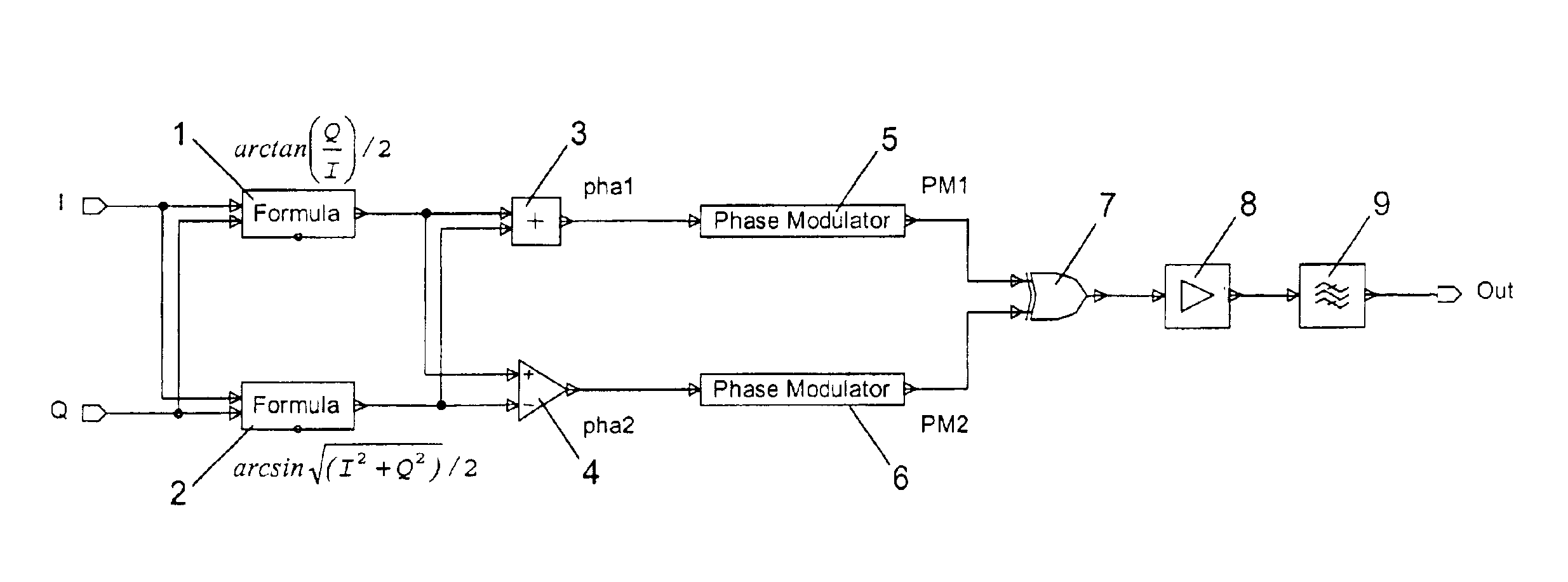
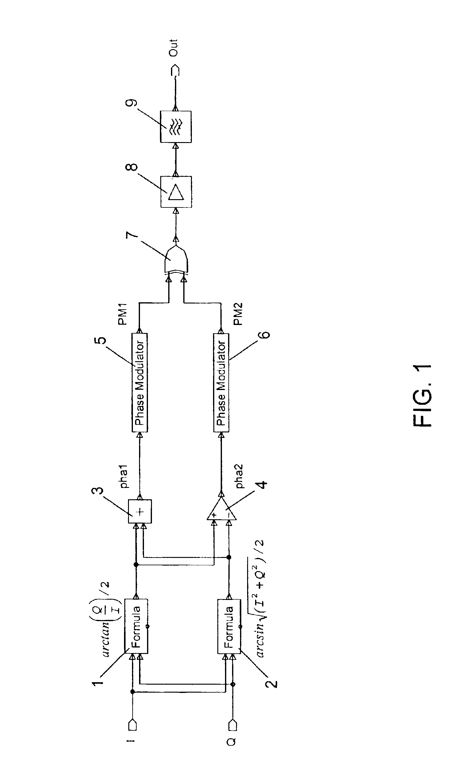
[0022]FIG. 1 presents an exemplary embodiment of a modulation system according to the invention, which can be employed in a transmitter for achieving a variable envelope modulation of a radio frequency signal based on amplitude varying control signals.

[0023]In the modulation system of FIG. 1, a first input ‘I’ is connected on the one hand to a first processing component 1 and on the other hand to a second processing component 2. A second input ‘I’ is equally connected on the one hand to the first processing component 1 and on the other hand to the second processing component 2. The output of the first processing component 1 is connected to a first input of a summing unit 3 and to a non-inverting input of a subtraction unit 4. The output of the second processing component 2 is connected to a second input of the summing unit 3 and to an inverting input of the subtraction unit 4. The first and the second processing component 1, 2, the summing unit 3 and the subtraction unit 4 constitut...


PUM


Abstract

In a modulation system, in order to provide a two-level signal with a desired modulation which is suited to be amplified by a switching mode power amplifier, the modulation system may include a first constant envelope modulator modulating a signal according to a first control signal, a second constant envelope modulator modulating a signal according to a second control signal, and a combining portion combining the output signal of the first and said second constant envelope modulator to a single, two-level pulse-width-modulated signal. The information which is to be represented by the modulation of the single, two-level pulse-width-modulated signal is coded in the first and the second control signals. The invention relates equally to a corresponding method for generating a modulated signal.

Description

FIELD OF THE INVENTION[0001]The invention relates to a modulation system and to a method for generating a modulated signal.BACKGROUND OF THE INVENTION[0002]Modulation systems are known from the state of the art for modulating a first signal based on a second signal, for instance for modulating a radio frequency carrier based on information that is to be transmitted in a cellular system.[0003]Due to the increasing requirements on spectral efficiency, variable envelope modulation methods have become more and more popular in cellular systems. With variable envelope modulation methods, however, the limited efficiency of conventional power amplifiers may cause heat and / or operation time problems in the transmitter equipment, in particular in thermally limited equipment like terminals. In order to reduce the amount of these effects, new transmitter architectures making use of switching mode power amplifiers have been proposed. Switching mode power amplifiers can theoretically approach a p...

Claims


Application Information

Patent Timeline
Patent Type & Authority Patents(United States)
IPC IPC(8): H03F1/02H03F1/06H03F3/217H04L25/49
CPCH03F1/02H03F1/0205H03F3/217H04L25/4902H03F2200/331H04L27/12H04L25/49
Inventor VARIS, JUKKAROSNELL, SEPPO
Owner NOKIA CORP
Learn More