
Process for circumferential magnetization of magnetoelastic shafts

a technology of magnetoelastic torque and circumferential magnetization, which is applied in the direction of magnets, magnets, instruments, etc., can solve the problems of degrading the performance of the transducer, difficult to control the magnetization profile, and extremely difficult to magnetize the shaft by conventional magnetization methods, so as to prevent the magnetization of parts

Inactive Publication Date: 2005-12-13
TEDRIVE HLDG
View PDF12 Cites 21 Cited by
  • Summary
  • Abstract
  • Description
  • Claims
  • Application Information

AI Technical Summary

Benefits of technology

[0011]The invention provides a method and apparatus for circumferentially magnetizing the active regions of torque transducer shafts for the measurement of torque applied to a shaft, preferably in an automotive steering mechanism. Specifically, the method and apparatus of the present invention address the disadvantages of conventional apparatus and methods of magnetizing torque transducer shafts by providing an apparatus and method that ensures substantially complete magnetization of the active regions of the transducer shaft.
[0016]In still another aspect, the apparatus contains shielding to prevent magnetization of portions of the shaft that should not be magnetized.

Problems solved by technology

With this technique, it is difficult to control the magnetization profile.
In addition, as a practical matter, it is extremely difficult to magnetize a shaft by conventional magnetization methods using polarizing magnets to a depth greater than about 1–2 mm because it is difficult to generate a strong enough magnetic field so far from the magnetic field source, due to the change in reluctance caused by the air gap between the magnet and shaft to be magnetized.
Moreover, the use of external polarizing magnets may result in uneven magnetization where the transducer material deepest within the shaft is insufficiently magnetized, leading to degraded transducer performance, such as reduced short term and long term sensitivity and the creation of “hot-spots”—nonuniformity in the transducer response.
This technique is also difficult to optimize, configure and control.
With hollow shafts of large diameter, cooperating internal as well as external polarizing magnets also may be required to obtain a uniform, full-depth polarization of the active region(s), thereby increasing the cost of the apparatus.

Method used


Image

  • Process for circumferential magnetization of magnetoelastic shafts
  • Process for circumferential magnetization of magnetoelastic shafts
  • Process for circumferential magnetization of magnetoelastic shafts

Examples


Embodiment Construction

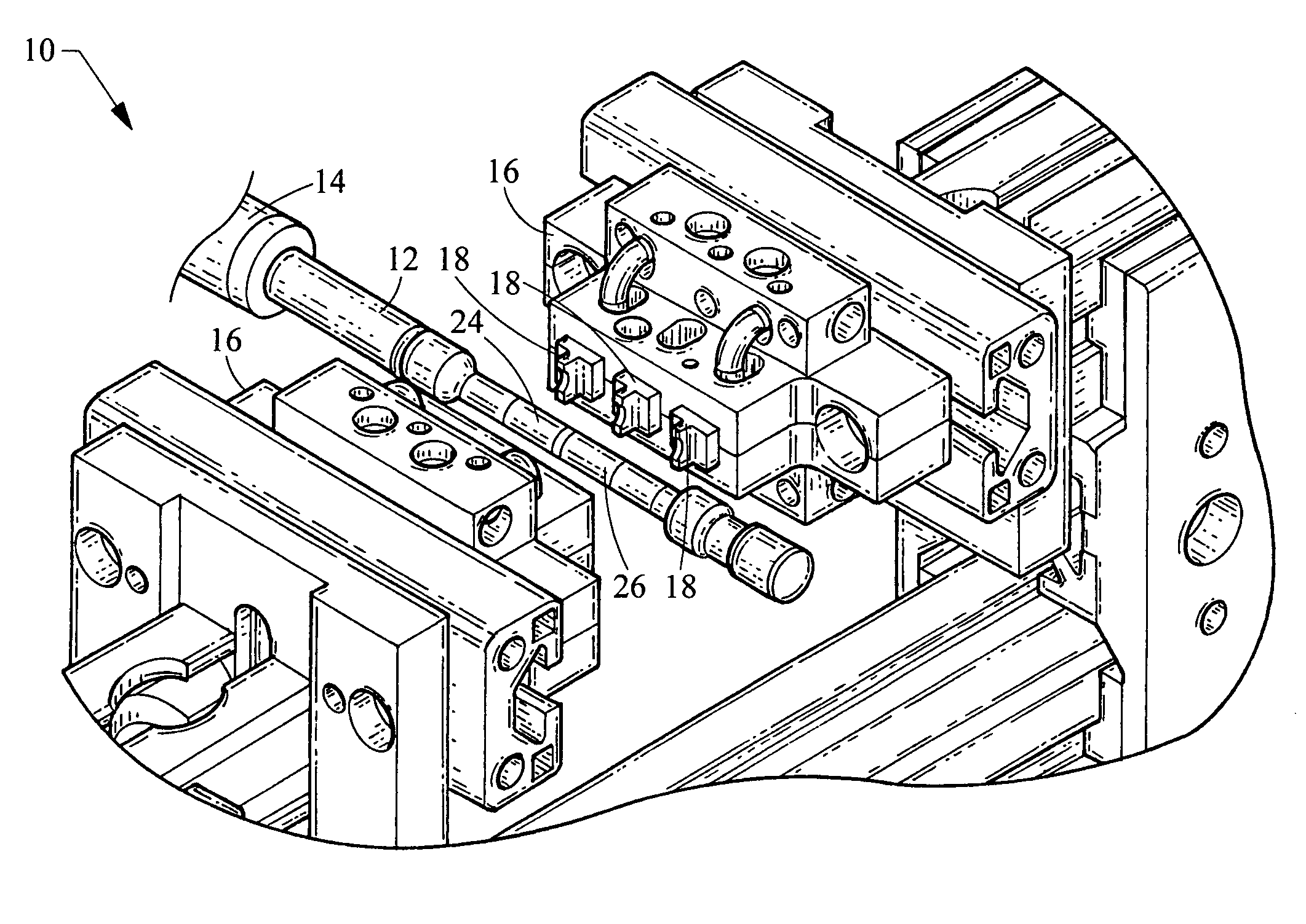
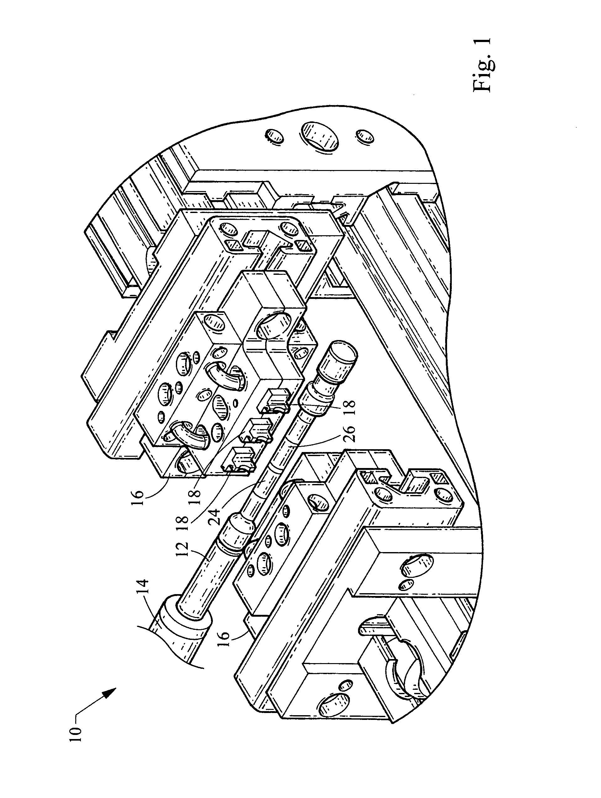
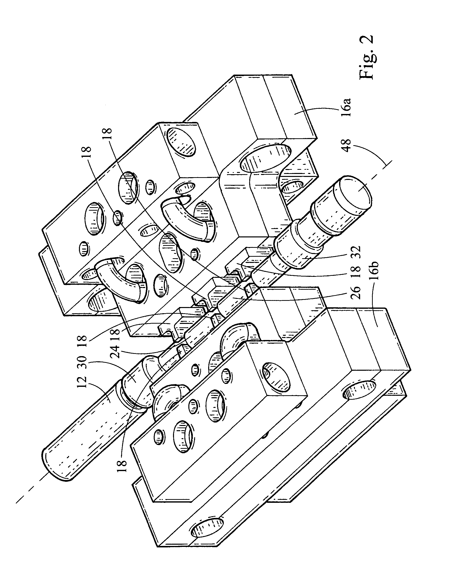
[0026]Referring first to FIG. 1, an apparatus for magnetizing a shaft 12 in accordance with the present application is shown generally at 10. The apparatus 10 generally comprises a fixture 14 mounted onto the apparatus 10 to hold the shaft 12. The fixture can be adapted to rotate the shaft 12 to provide better uniformity of the magnetization of the shaft 12. At least one magnetization head 16 is mounted onto the apparatus 10. The magnetization head 16 is radially moveable relative to the fixture 14.

[0027]The magnetization head 16 includes a plurality of brushes 18 mounted thereon. The brushes 18 have a distal end 20 that defines an internal diameter that is sized to circumferentially engage the shaft. Preferably, the brushes 18 are spring-loaded such that when the magnetization head is moved toward the fixture, the brushes 18 will engage the shaft 12 with an appropriate pre-load.

[0028]A buss bar 22 is connected to the brushes 18 to selectively supply an electric current through the ...


PUM

PropertyMeasurementUnit
diameteraaaaaaaaaa
diameteraaaaaaaaaa
diameteraaaaaaaaaa

Abstract

An apparatus for magnetizing selected portions of a shaft in a substantially circumferential direction includes a fixture mounted onto the apparatus adapted to receive a shaft to be magnetized, at least one magnetization head, the magnetization head being mounted moveably on the apparatus such that the magnetization head can be moved radially relative to the fixture, a plurality of brushes mounted onto the magnetization head, each brush having a distal end defining an internal diameter sized to circumferentially contact the shaft, the brushes being spring-loaded such that when the magnetization head is moved toward the fixture, each brush engages the shaft with proper pre-load force, and a buss bar, wherein the brushes are electrically connected to the buss bar for even distribution of electrical current to the brushes.

Description

FIELD OF THE INVENTION[0001]The present invention relates to an apparatus and method for magnetizing a shaft, and more particularly to an apparatus and method for circumferentially magnetizing magnetoelastic torque transducer shafts for providing a measure of torque applied to the shaft.BACKGROUND OF THE INVENTION[0002]In the control of systems having rotating drive shafts, the amount of torque applied to the drive shaft is an important parameter for control feedback. Therefore, the sensing and measurement of torque in an accurate, reliable and inexpensive manner has been a primary objective. For this purpose, non-contacting magnetoelastic torque transducers have been provided.[0003]Magnetoelastic torque transducers commonly have two features—1) a shaft which is ferromagnetic and magnetostrictive; and 2) a means for detecting or sensing the measure of torque applied to the shaft. Ferromagnetism ensures the existence of magnetic domains within the shaft and magnetostriction allows th...

Claims


Application Information

Patent Timeline
Patent Type & Authority Patents(United States)
IPC IPC(8): G01L3/10G01L5/22H01F13/00
CPCH01F13/003G01L3/103
Inventor LAIDLAW, JOHN FRANCIS
Owner TEDRIVE HLDG
Learn More