Imaging and analyzing parameters of small moving objects such as cells

a small moving object and parameter analysis technology, applied in the field of imagining moving objects or particles, can solve the problems of biological and medical applications that are currently impractical, and achieve the effects of broad flat flow, increased analysis rate, and improved analysis ra

Inactive Publication Date: 2005-12-13
CYTEK BIOSCI
View PDF42 Cites 114 Cited by
  • Summary
  • Abstract
  • Description
  • Claims
  • Application Information

AI Technical Summary

Benefits of technology

[0019]Still another aspect of the present invention is directed to a method for increasing the throughput or analysis rate of an imaging system that use a TDI detector. Binning can be used to achieve such an increase.
[0020]One embodiment employs a multi-tap TDI CCD camera to enable an increase in line rate readout rates. For example, if the instrument uses a 600 by 512 pixelated CCD detector, and the 600 row element detector includes six separate multispectral imaging channels that are read out utilizing one tap so that six separate taps are used to read off the six separate imaging channels, the speed of the camera can be increased by a factor of six.
[0021]Another embodiment uses broad flat flow to increase the rate of analysis. A rectangular cross sectional fluid channel is employed, instead of a square cross sectional core, to enable a broad flat flow to be achieved. A broad flat flow enables multiple objects to be imaged, which further increases the analysis rate.
[0022]Yet another embodiment of the invention uses binning of the vertical CCD elements, such that the number of rows decrease, thereby increasing the effective read out rate for the output signal of the TDI detector. The decrease in vertical image resolution provides a substantial increase in analysis rate. It is important to note that the binning is only in the vertical direction, and that there is no binning in the horizontal direction.

Problems solved by technology

There are a number of biological and medical applications that are currently impractical due to limitations in cell and particle analysis technology.

Method used


Image

  • Imaging and analyzing parameters of small moving objects such as cells
  • Imaging and analyzing parameters of small moving objects such as cells
  • Imaging and analyzing parameters of small moving objects such as cells

Examples


second preferred embodiment

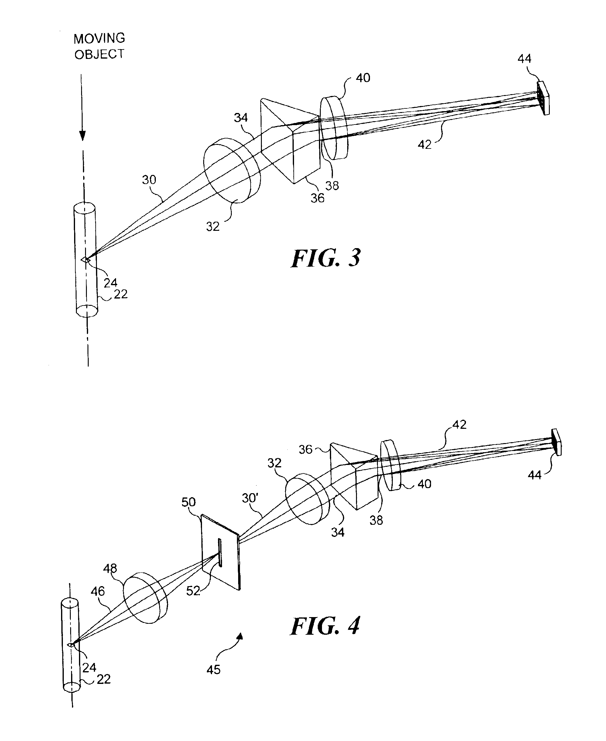
[0071]FIG. 4 illustrates an imaging system 45, which is a second preferred embodiment in connection with the present invention and which is similar in many ways to imaging system 20. However, imaging system 45 is a confocal embodiment that includes a slit 52 that substantially prevents extraneous light from reaching TDI detector 44. In imaging system 45, light 46 from object 24 is focused by an objective lens 48 onto a slit 52. Slit 52, as shown in FIG. 4, is sufficiently narrow to block light, which is not focused onto the slit by objective lens 48 from passing through the slit. Light 30′ passes through the slit and is collected by collection lens 32 as discussed above, in regard to imaging system 20. Collected light 34 is spectrally dispersed by prism 36, and is imaged by imaging lens 40 onto TDI detector 44, also as discussed above. By excluding light other than that from object 24 from reaching TDI detector 44, the TDI detector produces an output signal that corresponds only to ...

third preferred embodiment

[0080]A third preferred embodiment of an imaging system in connection with the present invention is a stereoscopic arrangement 70 of the first preferred embodiment, as illustrated in FIG. 6. This arrangement enables the imaging of the object from two different directions in order to distinguish features that would otherwise overlap when viewed from a single direction. While the third preferred embodiment can be employed for objects on moving substrates such as microscope slides, it is particularly useful for analyzing multi-component objects in solution, such as cells containing FISH probes. Such probes appear as point sources of light anywhere within the cell's three-dimensional nucleus. In some cases, two or more FISH probes may appear in an overlapping relationship along the optical axis of the imaging system. In such cases, one of the FISH probes may obscure the others, making it difficult to determine the number of probes present in the cell. This consideration is a key factor ...

fourth preferred embodiment

[0086]FIGS. 8A and 8B show two different views of a fourth preferred embodiment, which is an imaging system 90 that produces a scattered pattern image of object 24 on TDI detector 44. Light 30 from object 24 passes through collection lenses 32a and 32b, and collected light 34 is directed onto a cylindrical lens 92, as in the previous embodiments. Cylindrical lens 92 focuses light 94 on TDI detector 44, generally along a line that is aligned with a central axis 96 of cylindrical lens 92. Central axis 96 is shown in FIG. 8B, and it will be apparent that it is orthogonal to the direction in which object 24 moves through or relative to the imaging system. As object 24 moves downwardly, relative to its disposition as shown in FIG. 8A, the focus of cylindrical lens 92 on TDI detector 44 moves upwardly. Cylindrical lens 92 thus distributes an image of the object along a row or rows of the light sensitive regions or pixels of TDI detector 44.


PUM

PropertyMeasurementUnit
angleaaaaaaaaaa
angleaaaaaaaaaa
widthaaaaaaaaaa

Abstract

Light from an object such as a cell moving through an imaging system is collected and dispersed so that it is imaged onto a plurality of separate detectors. The light is spectrally dispersed by a plurality of spaced-apart dichroic reflectors, each detector receiving light from a different one of the dichroic reflectors. Each dichroic filter reflects light of a different predefined color, passing light of other colors. The output signal from each detector is indicative of a different characteristic of the object. In one configuration, each detector is provided with a separate imaging lens. In another configuration, the detectors are spaced at varying distances from the corresponding dichroic reflectors, so that separate imaging lenses are not required.

Description

RELATED APPLICATIONS[0001]This application is a continuation-in-part application of a patent application Ser. No. 09 / 976,257, filed on Oct. 12, 2001, now U.S. Pat. No. 6,608,682, which is a continuation-in-part application of a patent application Ser. No. 09 / 820,434, filed on Mar. 29, 2001, now U.S. Pat. No. 6,473,176, which is a continuation-in-part application of patent application Ser. No. 09 / 538,604, filed on Mar. 29, 2000, now U.S. Pat. No. 6,211,955 issued Apr. 3, 2001, which itself is a continuation-in-part application of patent application Ser. No. 09 / 490,478, filed on Jan. 24, 2000, now U.S. Pat. No. 6,249,341 issued Jun. 19, 2001, which is based on a provisional application Ser. No. 60 / 117,203, filed on Jan. 25, 1999, the benefit of the filing dates of which is hereby claimed under 35 U.S.C. §120 and 35 U.S.C. §119(e). Patent application Ser. No. 09 / 976,257, noted above, is also based on provisional application Ser. No. 60 / 240,125, filed on Oct. 12, 2000, the benefit of th...

Claims


Application Information

Patent Timeline
Patent Type & Authority Patents(United States)
IPC IPC(8): C07B61/00C12Q1/68G01J3/28G01N15/02G01N15/10G01N15/14G01N21/03G01N21/05G01N21/64G01N21/85G02B7/28G02B21/00G02B27/00G02B27/14
CPCC12Q1/6816G01J3/2803G01J3/2823G01N15/147G01N15/1475G01N21/6428G01N21/6456G01N21/85G02B7/28G02B21/00G02B27/0012G02B27/1013G02B27/144G02B27/145G02B27/148G01N15/1434G01N2015/0294G01N2015/1006G01N2015/1443G01N2015/1472G01N2015/1479G01N2015/1486G01N2015/1488G01N2021/052G01N2021/058C12Q2563/179C12Q2563/107
Inventor ORTYN, WILLIAM E.BASIJI, DAVID A.
Owner CYTEK BIOSCI
Why Eureka
Try Eureka