Power saving apparatus in an appliance

a technology for power saving apparatus and portable appliances, applied in mechanical power/torque control, dc source parallel operation, electric devices, etc., can solve the problems of increasing the total power consumption of the system, reducing the life span of the battery powering such systems, and not being able to effectively manage the power supply of the battery alarm. , to achieve the effect of reducing the total power consumption of the portable applian

Inactive Publication Date: 2005-12-13
LG ELECTRONICS INC
View PDF10 Cites 20 Cited by
  • Summary
  • Abstract
  • Description
  • Claims
  • Application Information

AI Technical Summary

Benefits of technology

[0015]Another object of the present invention is to provide a power saving apparatus in a portable appliance and power saving method thereof that interrupts power supply to less critical or user-sorted devices consuming power in the portable appliance.
[0016]Another object of the present invention is to provide a power saving apparatus in a portable appliance and power saving method thereof that reduces a total power consumption of the portable appliance by disconnecting a power supply to certain devices according to a scheme selected or predetermined by a user.

Problems solved by technology

Such development has generally added new devices, increasing the total power consumption of the system.
Because power management of the new devices is inadequate in the related art, however, the life span of batteries powering such systems has been significantly reduced.
The battery alarm is not an effective power supply management technique.
However, APM fails to meet the user's needs for active power supply management of peripheral devices attached to a PC that are not ACPI compatible.
For instance, APM fails to consider compatibility of various communication tools that will be available for PCs in the near future.
Thus, systems in the related art are not sufficiently equipped with power supply management functions that can extend an operation time of a battery supply.

Method used


Image

  • Power saving apparatus in an appliance
  • Power saving apparatus in an appliance
  • Power saving apparatus in an appliance

Examples


Embodiment Construction

[0028]Reference will now be made in detail to preferred embodiments according to the present invention, examples of which are illustrated in the accompanying drawings.

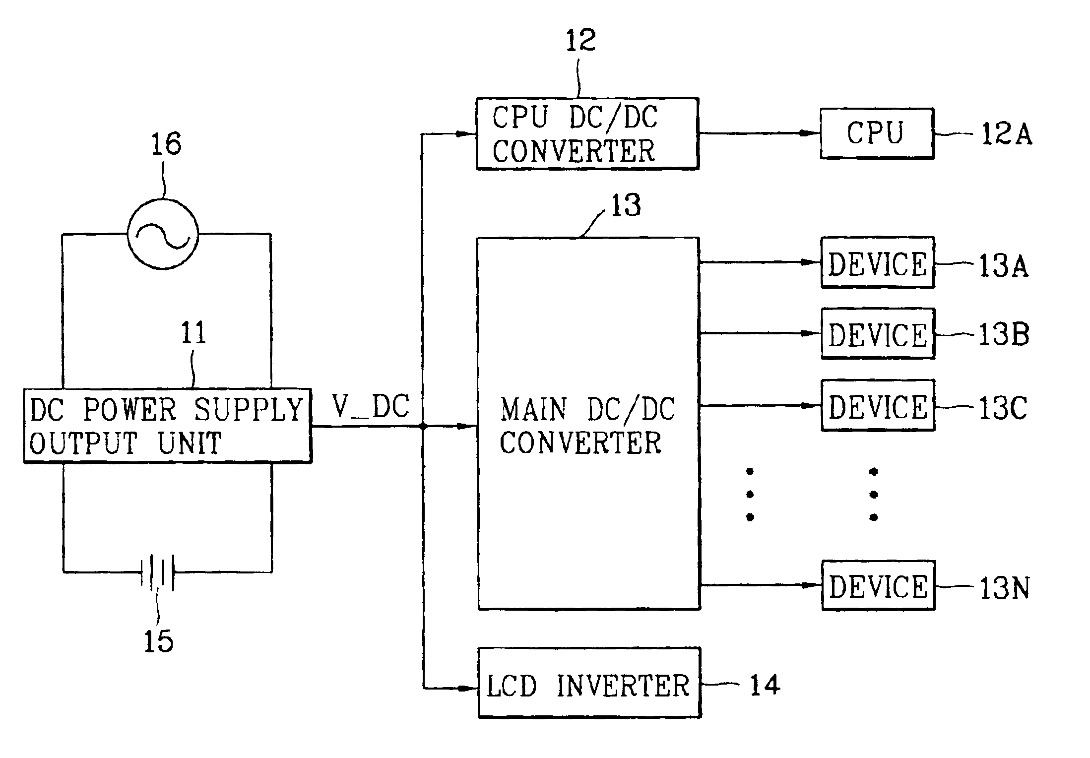
[0029]FIG. 3 illustrates a block diagram of a preferred embodiment of a power supply apparatus in a notebook computer to which a power saving method according to the present invention can be applied. The power supply apparatus may include a DC power supply output unit 31 outputting a battery voltage or a DC voltage of a predetermined level converted from an AC power supply 37, a CPU DC / DC converter 32 supplying a DC voltage required for a CPU 32A by converting the DC voltage V_DC outputted from the DC power supply output unit 31, and a main DC / DC converter 33 supplying DC voltages required for driving devices 33A to 33N respectively by converting the DC voltage V_DC. An LCD inverter 34 can supply an LCD with a driving voltage by converting the DC voltage V_DC, and power switches 35A to 35N preferably turn on / off powers...


PUM


Abstract

Disclosed a system and method of lengthening a life span of a battery power supply in an appliance such as a portable appliance, notebook computer or the like. A power saving method in an appliance includes displaying a user set-up menu for a power saving on a screen by respectively checking systems in the appliance, outputting a control command to a micro-controller in accordance with power saving contents determined on the user set-up menu by a user, and executing a power saving program set up by the user in accordance with the control command of the micro-controller.

Description

[0001]This application is a Divisional of U.S. patent application Ser. No. 09 / 994,840, filed Nov. 28, 2001, now U.S. Pat. No. 6,751,561, which claims priority to Korean Patent Application No. 71284 / 2000, filed Nov. 28, 2000. The entire disclosure of the prior application is considered as being part of the disclosure of the accompanying application and is hereby incorporated by reference herein.BACKGROUND OF THE INVENTION[0002]1. Field of the Invention[0003]The present invention relates to an apparatus and method for lengthening a life span of a battery power supply in a portable appliance, and more particularly to improved power management.[0004]2. Background of the Related Art[0005]Many efforts have been made to develop multimedia and personal / notebook computers having various new functions. Such development has generally added new devices, increasing the total power consumption of the system. Many portable systems are optionally powered by batteries. Because power management of th...

Claims


Application Information

Patent Timeline
Patent Type & Authority Patents(United States)
IPC IPC(8): G01R15/00G01R19/00G06F1/32G06F19/00
CPCG06F1/3203G06F1/3287Y02B60/1282Y02B60/1217Y02D10/00G06F1/32
Inventor OH, JANG GEUN
Owner LG ELECTRONICS INC
Why Eureka
Try Eureka