Eureka AIR delivers breakthrough ideas for toughest innovation challenges, trusted by R&D personnel around the world.

Apparatus and methods for connecting modules using remote switching

a technology of remote switching and apparatus, applied in the direction of electrical apparatus casings/cabinets/drawers, instruments, and multiple processing units, can solve the problems of laborious and error-prone process of expanding the system at all, and the incremental expansion of single module units in conventional multi-module systems is not allowed. , to achieve the effect of reducing the likelihood of connection errors, reducing the need, and increasing the connection density

Inactive Publication Date: 2005-12-13
FUTUREWEI TECH INC
View PDF37 Cites 2 Cited by
  • Summary
  • Abstract
  • Description
  • Claims
  • Application Information

AI Technical Summary

Benefits of technology

[0020]The module connection assembly alleviates the need for using wire cables. Accordingly, the operator does not need to search for the correct cables in a maze of cables, plug and unplug cables, and work with cables in tight places. Additionally, the present invention allows for higher connection density, i.e., connections per inch or board perimeter than that of a typical conventional cabled system.
[0021]Furthermore, the module connection assembly is remotely switchable so that the operator is not hindered by space limitations. Accordingly, the topology can be reconfigured without needing to gain access to the back of the system. Also, with remote actuation, it is easy to make sure that the correct paths are being modified when changing the topology of the system. That is, the remote activation reduces the likelihood of connection errors (e.g., plugging a cable into an incorrect location, or incorrectly plugging a cable into a correct location). Additionally, the cost per signal is substantially lower than with a cable. Furthermore, signal integrity is preserved, i.e., the signal remains in a good 100-ohm differential transmission line environment through the connector. In contrast, a cable, and its two connectors, usually involve a significantly greater impedance discontinuity.

Problems solved by technology

Conventional multi-module systems generally do not allow incremental expansion in units of single modules.
In general, the poor extensibility of conventional machines is due to two factors.
First, it is often a laborious and error prone process to expand the system at all.
Second, some conventional machines also employ regular routing algorithms, such as e-cube (or dimension-order) routing, that only work in a regular (complete) torus or mesh network.
Accordingly, such systems could not be expanded incrementally.

Method used


Image

  • Apparatus and methods for connecting modules using remote switching
  • Apparatus and methods for connecting modules using remote switching
  • Apparatus and methods for connecting modules using remote switching

Examples


Embodiment Construction

[0041]A description of preferred embodiments of the invention follows.

[0042]The present invention connects together modules of a multi-module data processing system such as an internet router formed by a network of fabric routers, or a multicomputer system. Internet switch routers formed by networks of fabric routers are described in application Ser. No. 08 / 918,556, filed Aug. 22, 1997, the entire teachings of which are incorporated herein by reference. Multicomputer networks are described in detail in Dally, W. J., “Network and Processor Architectures for Message-Driven Computing,”VLSI and PARALLEL COMPUTATION, Edited by Suaya and Birtwistle, Morgan Kaufmann Publishers, Inc., 1990, pp. 140-218, the entire teachings of which are incorporated herein by reference.

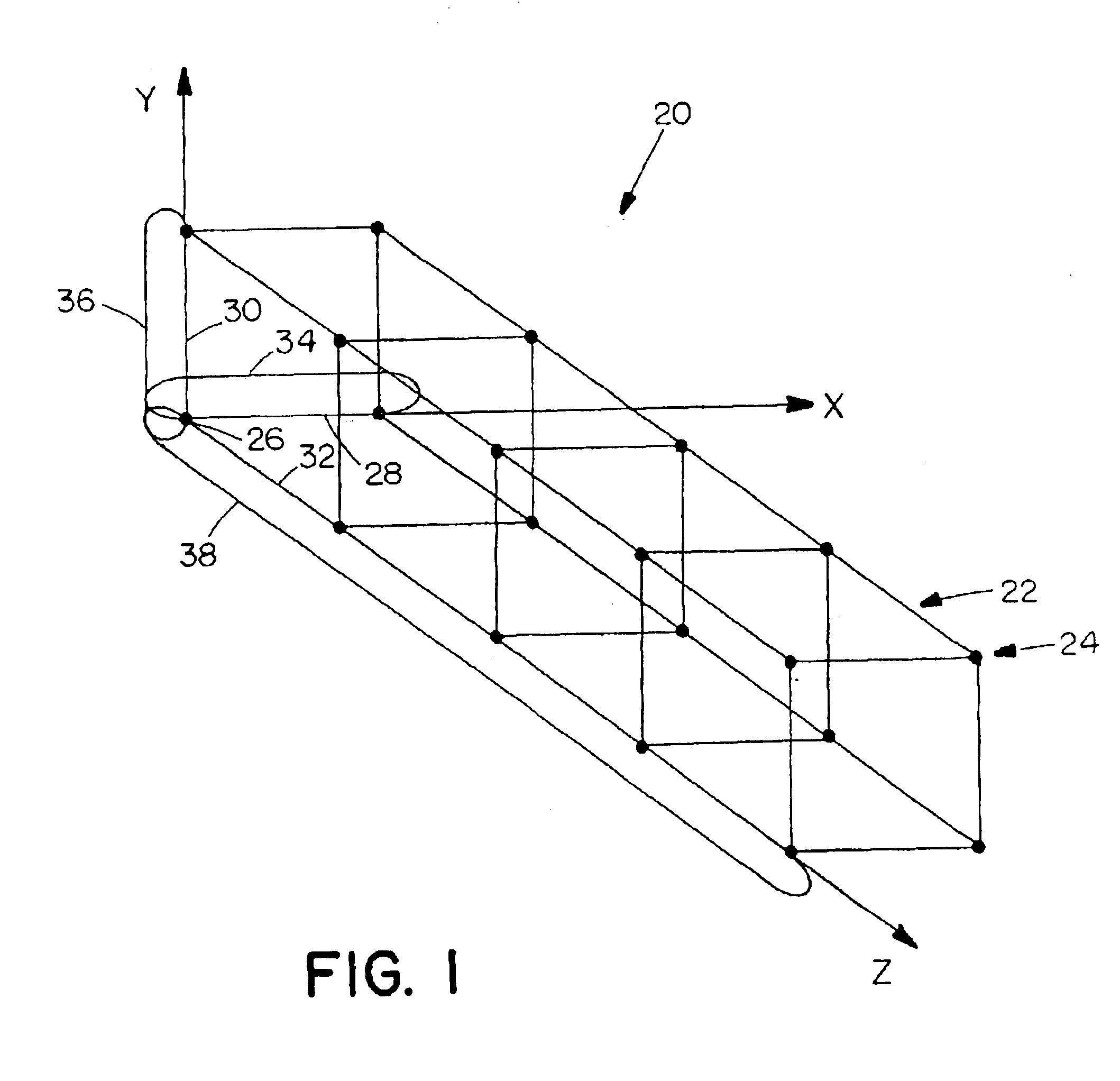
[0043]A logical view of a multi-module data processing system 20 (e.g., an internet router or a multicomputer system) is shown in FIG. 1. The system 20 includes links 22 and modules 24. The links 22 connect the modules 24 in ...


PUM


Abstract

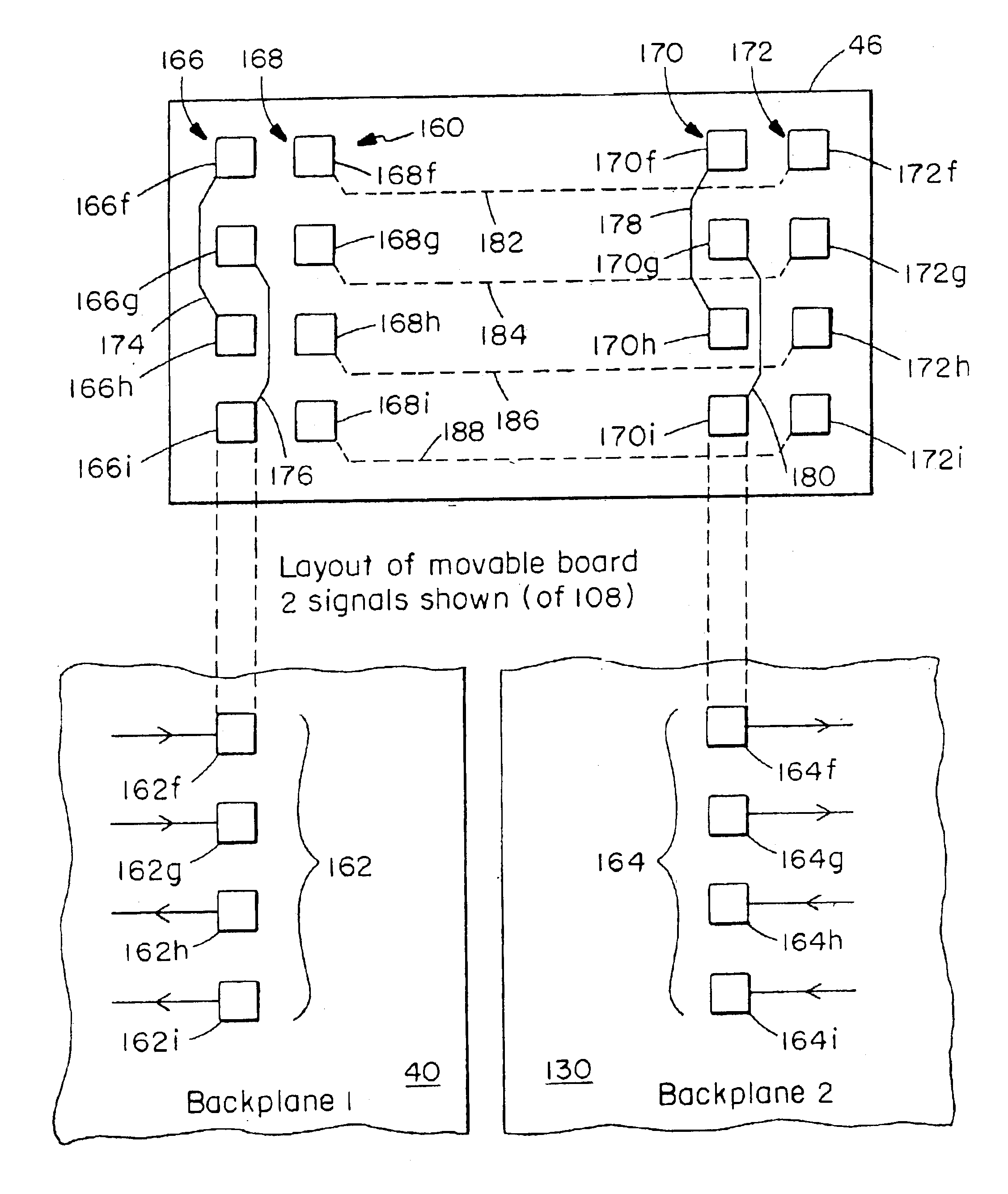
A module connection assembly connects modules in a torus configuration that can be changed remotely. In particular, a single module can be added to or deleted from the configuration by remotely switching from conducting paths that provide end-around electrical paths to conducting paths that provide pass-through electrical paths. The assembly includes two backplanes, a first set of module connectors for electrically connecting modules to one of the backplanes, and a second set of module connectors for electrically connecting modules to the other backplane. The assembly further includes configuration controllers. Each configuration controller selects between end-around electrical paths that electrically connect multiple module connectors of the first set to each other, and pass-through electrical paths that electrically connect module connectors of the first set to module connectors of the second set. Each configuration controller operates as a remotely configurable switch that configures a topology formed by the backplanes and the module connectors. In particular, by adding a single module, the topology can be expanded incrementally.

Description

RELATED APPLICATIONS[0001]This application is a continuation of application Ser. No. 09 / 765,138, filed Jan. 18, 2001 now U.S. Pat. No. 6,606,656, which is a continuation of application Ser. No. 09 / 083,722, filed May 22, 1998, now U.S. Pat. No. 6,205,532, which issued on Mar. 20, 2001. The entire teachings of the above applications is incorporated herein by reference.BACKGROUND OF THE INVENTION[0002]Computer systems come in a variety of topologies. Systems that include multiple data processing modules (or nodes) often have complex topologies. The interconnection assemblies that connect the modules of such topologies are often complicated, as well. In particular, it is a demanding task for an interconnection assembly to provide several connections (or links) to each module, as required by certain systems having mesh-shaped and torus-shaped configurations.[0003]A typical multi-module computer system has an interconnection assembly that includes a backplane, module connectors and flexib...

Claims


Application Information

Patent Timeline
Patent Type & Authority Patents(United States)
IPC IPC(8): G06F15/173G06F15/80
CPCG06F15/17343G06F15/8023
Inventor CARVEY, PHILIP P.DALLY, WILLIAM J.DENNISON, LARRY R.
Owner FUTUREWEI TECH INC
Why Eureka
Eureka Blog
Learn More