Rebuilding redundant disk arrays using distributed hot spare space

a hot spare space and array technology, applied in the field of disk storage subsystems, can solve the problems of arrays that had a disk drive failure at the same redundancy level, arrays that had a disk drive failure, etc., and achieve the effect of performing faster

Inactive Publication Date: 2005-12-13
AVAGO TECH WIRELESS IP SINGAPORE PTE
View PDF11 Cites 58 Cited by
  • Summary
  • Abstract
  • Description
  • Claims
  • Application Information

AI Technical Summary

Benefits of technology

[0010]There are two advantages to having the hot spare space distributed over all disk drives. First, the dedicated standby disk that would otherwise have been idle during user I / O is now an active part of the array, causing the array to perform faster because it has more disk drives. Second, the standby disk drive that would have been idle during user I / O cannot fail undetected because, with the invention, all disk drives are in constant use, and not standing by idle.
[0011]More particularly, a method and system allows the distribution of hot spare space across multiple disk drives that also store the data and redundant data in a fully active array of redundant independent disks, so that an automatic rebuilding of the array to an array of the identical level of redundancy can be achieved with fewer disk drives.
[0012]The method configures the array with D disk drives of B physical blocks each. N user data and redundant data blocks are allocated to each disk drive, and F free blocks are allocated as hot spare space to each disk drive, where N+F<=B, and ((D−M)×F)>=N. Thus, rebuilding of data and redundant blocks of a failed disk drive in the free blocks of the remaining disk drives is enabled after M disk drive failures. As an advantage, the method and system according to the invention can correctly handle single failures, multiple sequential failures, and multiple concurrent failures.

Problems solved by technology

This leaves extra hot spare space on each disk drive to allow a new array to be built, with fewer disk drives, but the same redundancy level of the array that had a disk drive failure.
First, the dedicated standby disk that would otherwise have been idle during user I / O is now an active part of the array, causing the array to perform faster because it has more disk drives.

Method used


Image

  • Rebuilding redundant disk arrays using distributed hot spare space
  • Rebuilding redundant disk arrays using distributed hot spare space
  • Rebuilding redundant disk arrays using distributed hot spare space

Examples


Embodiment Construction

Configuring and Allocating a Redundant Array of Independent Disks

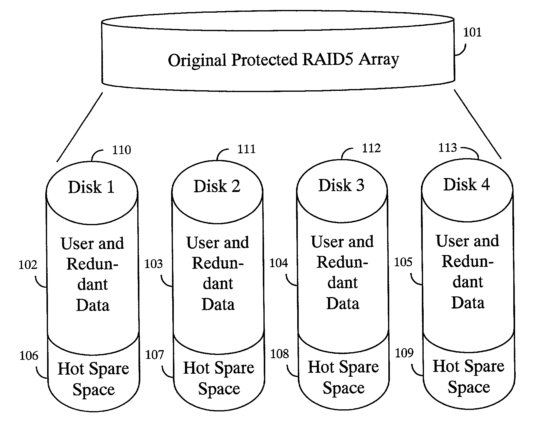
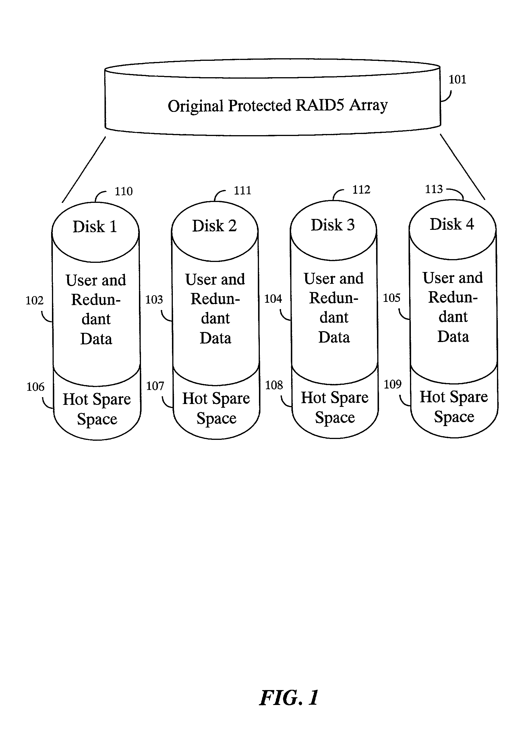
[0021]FIG. 1 shows an example RAID5 array 101 using four disk drives 110–113 with partitions configured and allocated according to the invention. The array 101 is configured by allocating user and redundant data partitions 102–105 and hot spare space partitions 106–109 distributed over all four disk drives in active use. The hot spare space partitions are used in the event of a disk failure.

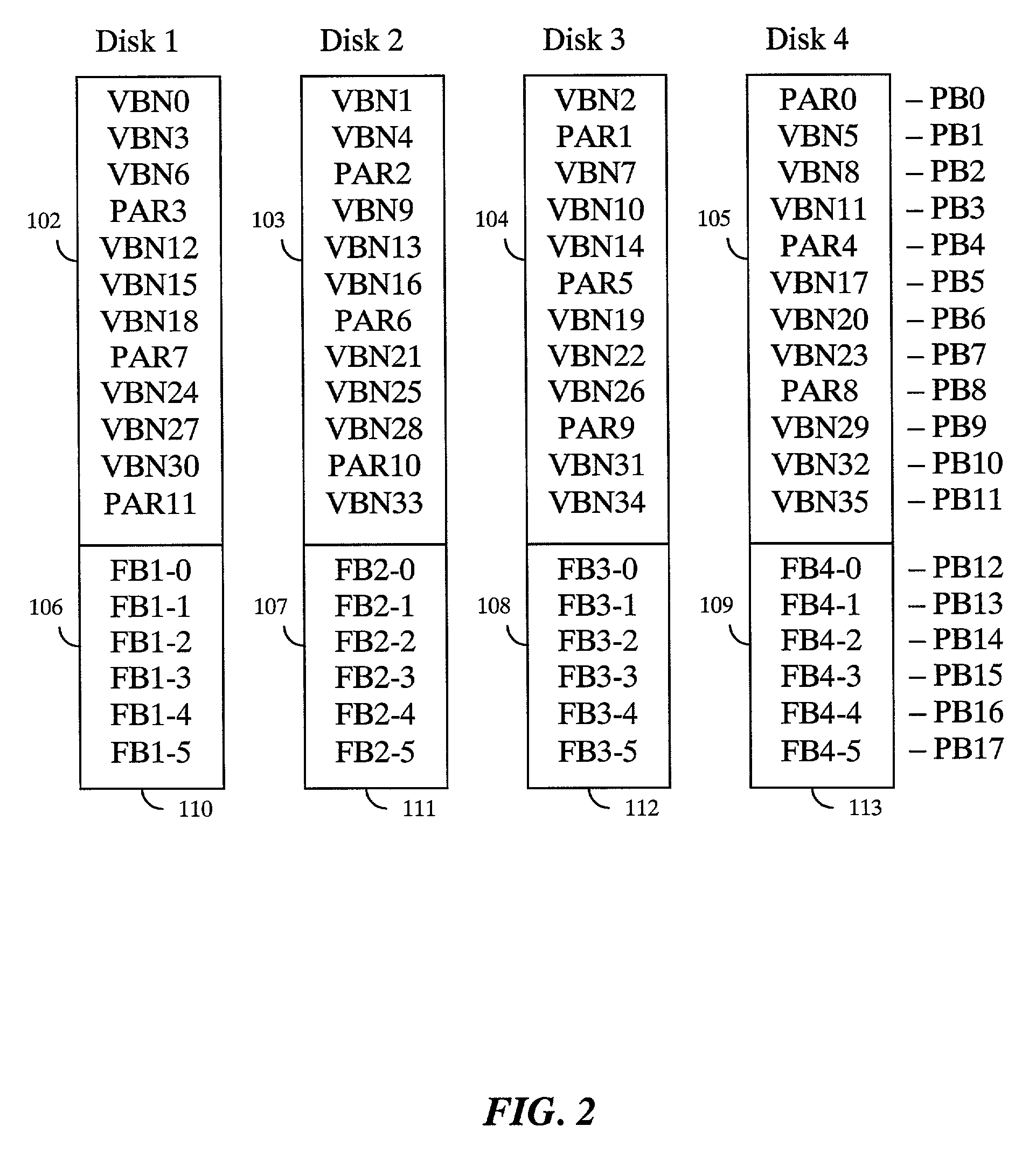
[0022]FIG. 2 shows block level details of the allocations of various partitions 102–109 of the disk drives 110–113. Each disk drive has, for example, eighteen physical blocks that are labeled on the right as PB0–PB17. The RAID5 array, presents the data to the user by mapping blocks accessed by the user to the physical blocks on the disk drive. Those blocks are known as virtual blocks, each having a virtual block number labeled VBN0–VBN35 for an array of thirty-six virtual blocks.

[0023]The RAID5 array also generates and maintains red...


PUM


Abstract

A method and system that allows the distribution of hot spare space across multiple disk drives that also store the data and redundant data in a fully active array of redundant independent disks, so that an automatic rebuilding of the array to an array of the identical level of redundancy can be achieved with fewer disk drives. The method configures the array with D disk drives of B physical blocks each. N user data and redundant data blocks are allocated to each disk drive, and F free blocks are allocated as hot spare space to each disk drive, where N+F<=B, and ((D−M)×F)>=N. Thus, rebuilding of data and redundant blocks of a failed disk drive in the free blocks of the remaining disk drives is enabled after M disk drive failures.

Description

FIELD OF THE INVENTION[0001]This invention relates generally to the field of disk storage subsystems, and more particularly to redundant arrays of independent disks (RAID) subsystems.BACKGROUND OF THE INVENTION[0002]Most modem, mid-range to high-end disk storage subsystems are arranged as redundant arrays of independent disks (RAID). A number of RAID levels are known. RAID-1 includes sets of N data disks and N mirror disks for storing copies of the data disks. RAID-3 includes sets of N data disks and one parity disk. RAID-4 also includes sets of N+1 disks, however, data transfers are performed in multi-block operations. RAID-5 distributes parity data across all disk drives in each set of N+1 disk drives. At any level, it is desired to have RAID subsystems where an input / output (I / O) operation can be performed with minimal operating system intervention.[0003]One of the most important aspects of any RAID subsystem is its ability to withstand a disk drive failure. To implement this fea...

Claims


Application Information

Patent Timeline
Patent Type & Authority Patents(United States)
IPC IPC(8): G06F11/00G06F11/10H04L1/22
CPCG06F11/10G06F11/1076G06F2211/1028
Inventor ARNOTT, RANDY M.WONG, JEFFREY T.
Owner AVAGO TECH WIRELESS IP SINGAPORE PTE
Why Eureka
Try Eureka