Apparatus and method for heating fluids

Inactive Publication Date: 2005-12-20
THOMA CHRISTIAN HELMUT
View PDF27 Cites 22 Cited by
  • Summary
  • Abstract
  • Description
  • Claims
  • Application Information

AI Technical Summary

Benefits of technology

[0015]It is therefore an aspect of this invention to be able to rapidly and successively alter and disrupt the spiral path of fluid flowing between the rotating and stationary elements in the passage gap region as it passes across these depressions which during operation of the device may become emptied or largely emply vessels of vaccum pressure, and where the deployment of openings or depression zones in the rotating disc assembly acts can divert a quantity of the passing fluid over the disc into these openings or depression zones for the formation of cavitation vortices inside these voids and their attendant shock waves and water hammer effects in the fluid. The fluid once subjected to water hammer returns back to the fluid passage gap region with an increase in temperature and this continues in a continuous process until the fluid eventually reaches the periphery of the disc from where it is directed to exit the device. As such, each of said openings or depression zones becomes in effect individual heating chambers for the device. For certain applications, some or all of such individual heating chambers may be inclined with respect to the longituinal axis of the device or otherwise communicated in series for the creation of an amplified cavitational effect by the device.
[0016]As there also would b

Problems solved by technology

Although some heating of the fluid is likely to occur naturally, due to the shearing effect on the fluid between the static and dynamic opposing fluid boundary surfaces, as w

Method used


Image

  • Apparatus and method for heating fluids
  • Apparatus and method for heating fluids
  • Apparatus and method for heating fluids

Examples


Example

DETAILED DESCRIPTION OF THE SECOND EMBODIMENT OF THE INVENTION

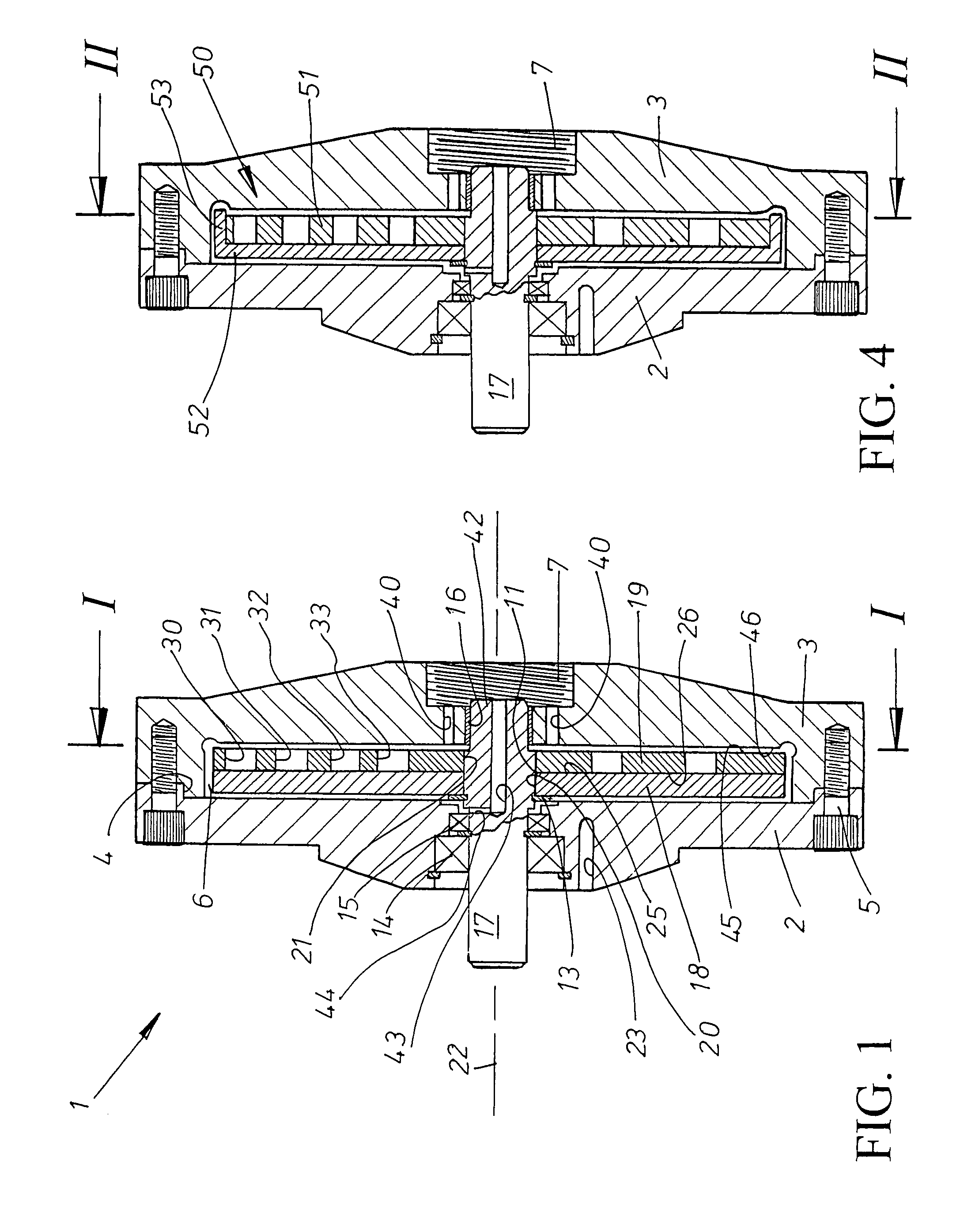
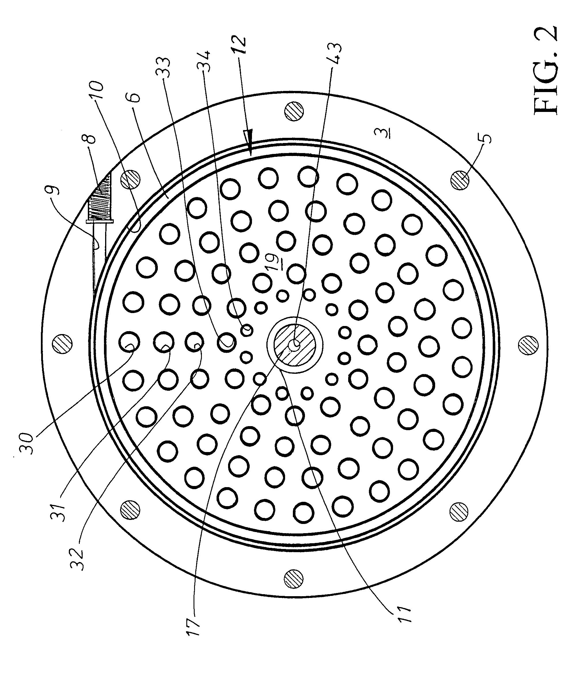
[0050]This embodiment of the present invention, depicted in FIGS. 4 to 8 differs in two major respects from the previously described first embodiment, firstly, that the rotor disc assembly is provided with a series of vanes, and secondly, specific to FIG. 8 where the parallel-walled holes are arranged to be inclined with respect to axis 22. As many of the other features of this embodiment are common to those already described, description is only necessary to show the main points of difference between these two embodiments of the invention. Further, as many of the components are identical to those described for the first embodiment, they carry the same same reference numeral.

[0051]The rotor disc assembly here denoted by arrow 50 is comprises of a perforated disc-shaped element 51 and an adjacent non-perforated element 52 referred to as the carrier element. The carrier element 52 really only differs from the flat disc-shap...

Example

DETAILED DESCRIPTION OF THE THIRD EMBODIMENT OF THE INVENTION

[0055]This embodiment of the present invention depicted in FIG. 9 differs with respect of the previously described embodiments in that the rotor disc assembly is comprised of two disc that in this case are both perforated, and where the relative position of the perforations in each disc are preferably staggered to the extent necessary in order that the holes are prevented from overlapping each other at the interface between the repective discs. The rotor disc assembly denoted by arrow 80 comprises a first perforated disc-shaped element 81 and a second perforated disc-shaped element 82, first perforated disc-shaped element 81 is provided with a plurality of openings denoted by reference numeral 83 and second perforated disc-shaped element 82 is provided with a plurality of openings denoted by reference numeral 84.

[0056]A proportion of the fluid entering the device at inlet 7 passes through fluid ports 40 towards surface 85 ...

Example

DETAILED DESCRIPTION OF THE FOURTH EMBODIMENT OF THE INVENTION

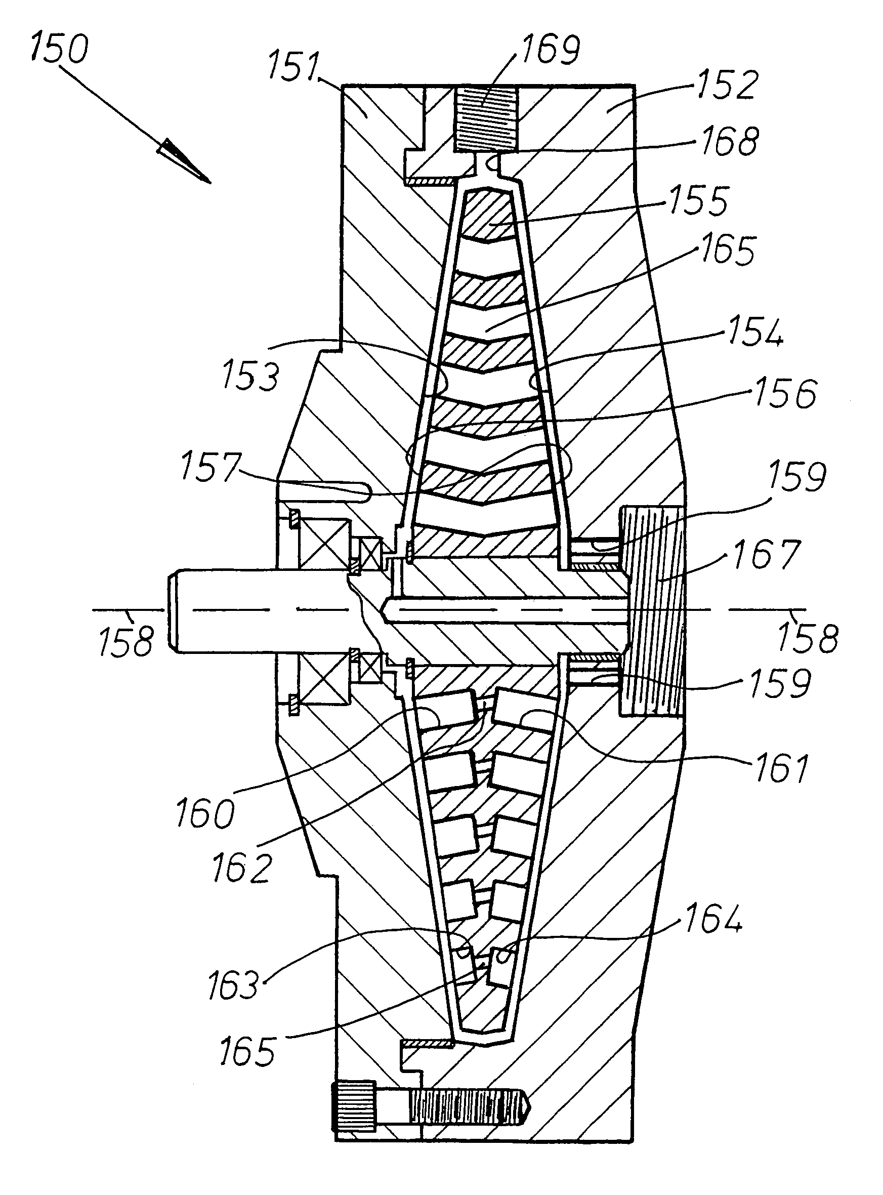
[0058]This embodiment of the present invention, depicted in FIGS. 10 to 13 differs in two main respects from the previously described first embodiment in that the rotor disc assembly is a single component element and where the cavitation inducing depression zones are no-longer configured in the form of parallel-sided holes. In the example here shown, the openings are bellmouthed and where they provide a large surface area at the surface of the disc rotor for the minimum distance of penetration, useful as the axial width of the the disc is small as compared to its diametrical size. The bellmouthed shape may easily be produced using the tip of a drill although a part-spherical shape using ball-nosed end mill cutter could be used to provide an acceptable alternative shape for such openings. The term bellmouthed is therefore intended to cover other shapes for the cavity of the opening that are unlike the parallel-sided holes ...


PUM


Abstract

An apparatus for heating a liquid comprising a housing having an internal chamber and a rotor disposed in said chamber. A drive shaft rotatably supported in the housing and extending into said chamber for imparting mechanical energy to the rotor. The rotor being provided with a series of openings generally arranged to be parallel to the rotational axis of the drive shaft. The rotor in the form of a disc and the housing formed with radial surfaces on either side of said rotor disc. The rotor may comprise a single disc or alternatively, a series of dics in a liminated formation. A fluid intake passage in said housing preferably arranged adjacent the center of the disc and a fluid exit passage, generally arranged to be circumeferntially outwards of said disc.

Description

BACKGROUND OF THE INVENTION[0001]The invention relates generally to the heating of liquids, and specifically to those devices wherein rotating elements are employed to generate heat in the liquid passing through them.[0002]Of the various configurations that have been tried in the past, types employing rotors or other rotating members are known, one being the Perkins liquid heating apparatus disclosed in U.S. Pat. No. 4,424,797. Perkins employs a rotating cylindrical rotor inside a static housing and where fluid entering at one end of the housing navigates through the annular clearance existing between the rotor and the housing to exit the housing at the opposite end. The fluid is arranged to navigate this annular clearance between static and non-static fluid boundary guiding surfaces, and Perkins relies principally on the shearing effect in the liquid, causing it to heat up.[0003]An example of a frictional method for producing heat for warming a fluid is the Newman apparatus disclos...

Claims


Application Information

Patent Timeline
IPC IPC(8): F24J3/00
CPCF22B3/06F24J3/003F24V40/00
Inventor THOMA, CHRISTIAN HELMUT
Owner THOMA CHRISTIAN HELMUT
Why Eureka
Try Eureka