Corrosive materials present special handling and disposal problems in that traditional piping systems, which include steel, iron,
copper and various plastic pipes, connectors and fixtures, are incapable of handling many corrosives due to the chemical reactivity or
solubility of these materials.
Corrosive materials, including
strong acids, strong bases, and strong solvents would, sooner or later, “eat through” or otherwise destroy these materials, resulting in their failure.
Most notably, glass piping is extremely brittle.
Glass piping is also very inflexible.
Stress applied to glass tubing during the course of installation (due to dropping, overtightening of coupling devices, deflections from “straight” connections between glass components and other stresses occasioned by both proper and improper installations) or in the course of use, often leads to cracks, fractures and breaks.
Such breaks are often difficult to repair due to the rigidity and
fragility of glass
pipe sections adjoining the broken section.
These disadvantages make the installation, maintenance and use of glass piping systems difficult and expensive.
These disadvantages also lead to environmental and workplace hazards which are considered undesirable by regulatory agencies such as the EPA and OSHA.
However, certain Teflon piping systems currently used in industry also have certain disadvantages for large
system applications.
Such field threading is technically difficult and is often performed improperly, leading either to wasted
pipe (if the improper threading is detected) or worse, less than adequate sealing between sections (if the improper threading is not detected).
The threaded joints can also be difficult to join properly with their potential for cross-threading, or over or under tightening.
Threaded Teflon piping sections are also difficult to replace or repair because threaded pipes are not easily disassembled.
This is because pipe sections cannot individually be unthreaded (unscrewed) from neighboring sections without necessitating disassembly of other sections “down the line” and / or “up the line”.
This problem, while always troublesome due to cost and time expenditures, is particularly vexing in long piping systems having many sequential joints.
The result is that thicker, heavier and thus more expensive piping must be employed.
These systems are generally not found not suitable for the applications in which threaded systems, have historically been used because they are often too small, and / or require complex and difficult to use field
welding equipment, and / or are much more expensive, and / or are very thin-walled, allowing too much
permeation, and / or are not sufficiently rigid to permit installation of systems that employ gravity draining.
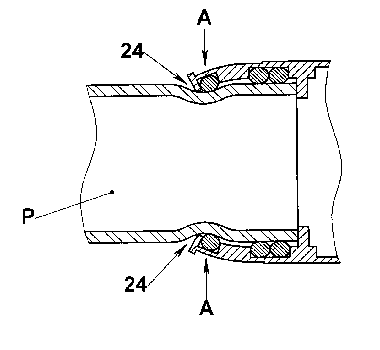
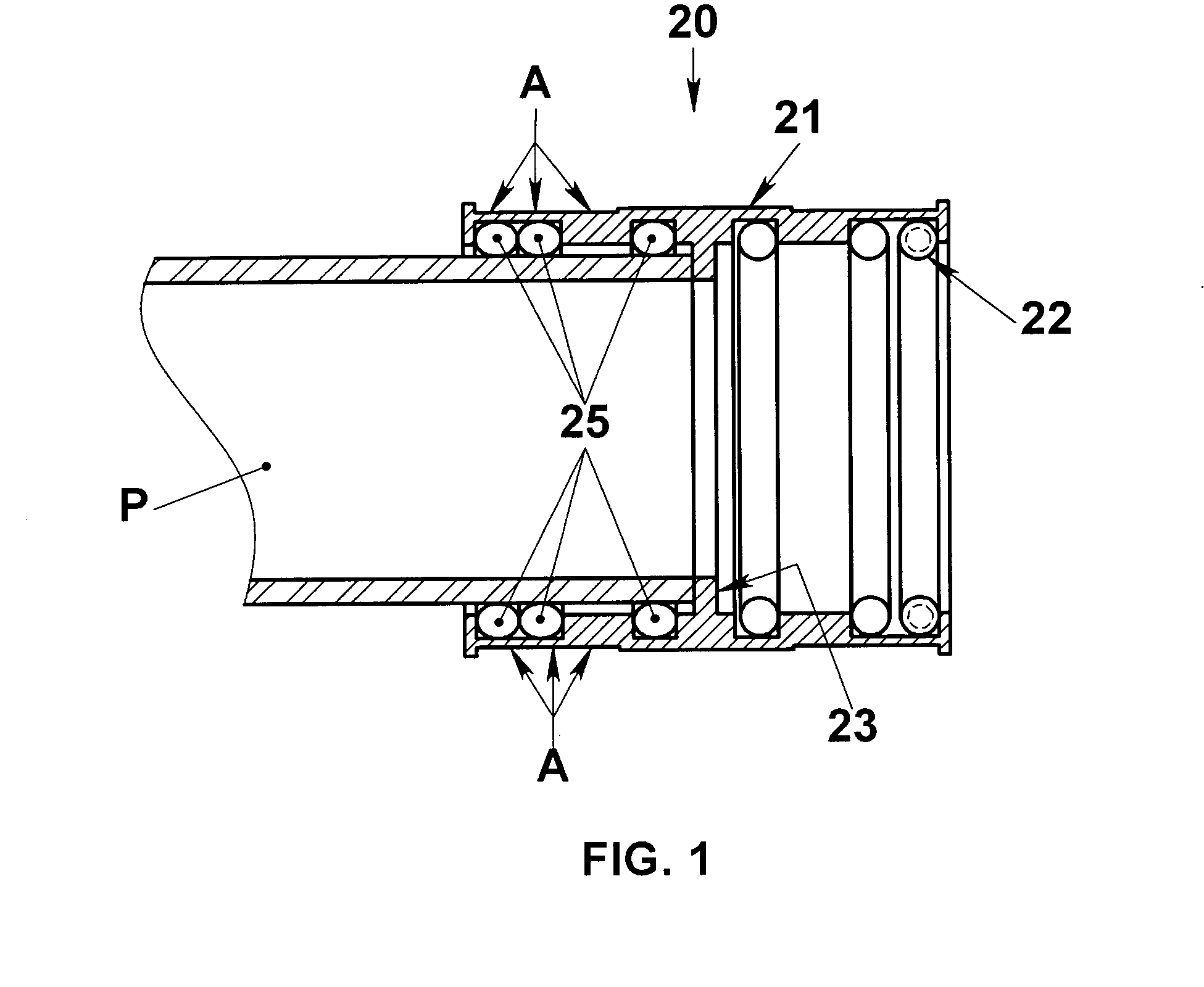
There is often difficulty connecting the Teflon piping or a P-trap to a glass sink.
Moreover, excess tightening of a coupling device to ensure the primary seal holds is of very little value, since the
brittleness of the glass limits the possible degree of tightening.
After installation, the rubber seal becomes corrupted and fails.
Thus, there is no glass-to-Teflon coupling device in which effective primary and secondary seals are capable of being formed.
Although beading geometry helps in forming a primary seal between the walls of the coupling device, it also significantly hinders the formation of a secondary seal.
The larger
diameter of the bead makes the presence of additional ribs “behind” where the bead is to be inserted difficult (since the bead must be forced past any such ribs to be seated within the coupler).
Plastic deformation or “
creep” may cause difficulties in coupling Teflon pipes both to glass and to other Teflon piping.
Tightening a coupling device often works well initially but requires retightening to account for
creep caused by the original tightening.
In glass-to-Teflon connections the problem noted above with respect to an inability to overtighten due to glass
brittleness is exacerbated by plastic deformation.

