Methods and apparatus for generating local oscillation signals

a local oscillator and signal technology, applied in the field of generating local oscillator signals, can solve the problems of loss of revenue, loss of services, loss of central station control of signals, etc., and achieve the effects of reducing the overall cost of the system, preventing theft of services, and reducing equipment and costs

Inactive Publication Date: 2005-12-20
VERIZON PATENT & LICENSING INC
View PDF20 Cites 26 Cited by
  • Summary
  • Abstract
  • Description
  • Claims
  • Application Information

AI Technical Summary

Benefits of technology

[0019]Moreover, bi-directional communications may be effected by further arranging the system for transmitting second electrical signal(s) between the central location and the customer's premises, the electrical-to-optical converter being adapted for receiving the second electrical signal(s) at its input and for changing the downstream optical signal in correspondence to the second electrical signal(s), and the optical-to-electrical converter being adapted for converting the detected downstream optical signal into second electrical received versions of the second electrical signal(s) for use by the customer. For upstream communication to complete the bi-directional operational mode, the system may be arranged with an upstream electrical-to-optical converter, at the customer premises, for converting a third electrical signal(s) into an upstream optical signal, and for transmitting the upstream optical signal over the optical fiber at a second optical wavelength, and wherein the central location further includes an upstream optical-to-electrical converter for detecting the upstream optical signal and for converting the upstream optical signal to detected electrical versions of the third electrical signal(s). Typically the third electrical signal(s) is the counterpart to the second electrical signal(s) which, when paired, effect the bi-directional communication mode.
[0020]The system (disclosed in the “related applications” referenced above) in which the present invention may be used provides an improved fiber optic subscriber loop architecture which reduces the overall cost of the system and prevents theft of services. Such a system selectively transmits only information ordered by the subscriber to the subscriber premises and, thus, eliminates the need for scramblers (at the central office or network node) and descramblers (at the subscriber premises). This results in a reduction in equipment and cost of the overall system. Such an arrangement also prevents unauthorized use or access (i.e., theft) of information services by a subscriber premises.
[0021]In the systems (disclosed in the “related applications” referenced above), each of the selected signals may be mixed with a particular modulation signal of a particular frequency. These mixed selected signals may then be combined before being converted into an optical signal. It is an object of the present invention to generate local oscillator signals (e.g., signals generated by an oscillator) with which the selected signals may be mixed for upstream and downstream conversions. The present invention may generate such oscillator signals by dividing a pilot tone, such as an approximately 120 MHz pilot tone found on many cable TV systems. Oscillator signals for demodulating received selected signals may be similarly generated. Generating such oscillator signals in this way minimizes or eliminates unwanted “beat” frequencies, is relatively inexpensive to implement, minimizes phase noise and minimizes the complexity and number of components required for local oscillator circuitry.

Problems solved by technology

However, even with advancements in optical fiber telecommunication technology, theft of services remains a growing concern among information providers (e.g., cable television service providers).
The problem involves the fact that once a central station distributes signals in a general manner to a subscriber premises, the central station loses control of the signals.
As a result, such signals are exposed to theft which results in lost revenue.
Such systems however require additional equipment, specifically scramblers and descramblers, which increases their overall cost.
Because the processing and routing of TDM signals is typically accomplished utilizing electronics, a drawback of the Graves system is a need for optical-to-electrical and electrical-to-optical conversions and for controlled environmental vaults, power back-ups and maintenance.
However, such subscriber-type systems employing WDMs neither provide nor suggest any mechanism for selecting particular signals for delivery to a subscriber premises.
The decoding / encoding required by the customer's equipment is expensive.
Moreover, it is virtually impossible with such an arrangement to deliver tailored services, that is, subscriber-dependent services, to each individual subscriber.
That is, there is no ability to deliver to a given subscriber selected ones of the video channels composing the propagated downstream signal.
Consequently, there is the potential for theft of the services as alluded to above.
This is disadvantageous since high power components tend to be more costly.
Consequently, the Ogura system must be arranged with dispersion compensation, which adds to its complexity and cost.

Method used


Image

  • Methods and apparatus for generating local oscillation signals
  • Methods and apparatus for generating local oscillation signals
  • Methods and apparatus for generating local oscillation signals

Examples


second embodiment

2.4.2 Second Embodiment

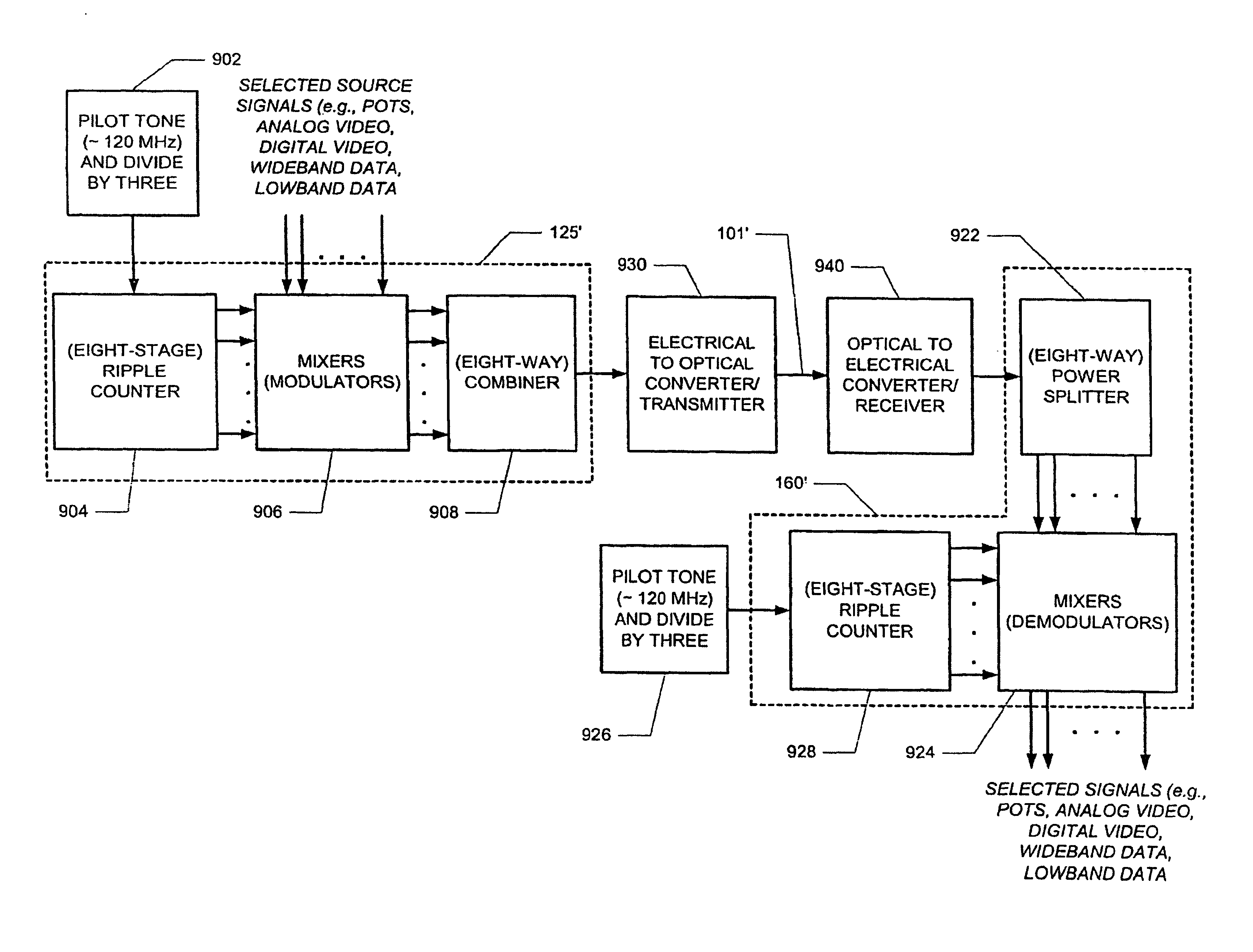
[0068]Recall from FIG. 5 that data transmission may occur from the central office to a subscriber via a central office RF combiner 125 and a subscriber receiver 160. Similarly, data transmission may occur from the subscriber to the central office via a subscriber RF combiner 170 and central office receiver 140. FIGS. 9 and 10 illustrate exemplary embodiments which facilitate data transmission from the central office to the subscriber and from the subscriber to the central office, respectively.

[0069]In the following exemplary embodiment, it is assumed that the downstream optical wavelength is 1310 nm and the upstream optical wavelength is 1550 nm. In this way, the two streams can use the same fiber and yet be separated. The downstream (e.g., CATV) bandwidth may be provisioned as follows: the band from 54 MHz to 600 MHz for analog video and 600 MHz to 750 MHz for digital video. All of these channels may be combined in the RF domain utilizing cable TV channel com...


PUM


Abstract

Generating oscillator signals with which selected signals may be mixed. Such oscillator signals may be generated by dividing a pilot tone, such as a 120 MHz pilot tone found on many cable TV systems. Oscillator signals for demodulating received selected signals may be similarly generated.

Description

RELATED APPLICATIONS[0001]This application is a continuation-in-part of U.S. patent application Ser. No. 09 / 283,400, filed on Apr. 1, 1999 now U.S. Pat. No. 6,538,781 and entitled “Multimedia Distribution System Using Fiber Optic Lines” which is a continuation-in-part of U.S. patent application Ser. No. 08 / 806,090, filed Feb. 25, 1997 issued as U.S. Pat. No. 6,055,077 on Apr. 25, 2000 and entitled “Multimedia Distribution System Using Fiber Optic Lines”. Each of these applications and the patent are incorporated herein by reference and priority is claimed to these applications under 35 U.S.C. §120.FIELD OF THE INVENTION[0002]The present invention concerns generating local oscillator signals which may be used in a multimedia system (disclosed in the “related applications” referred above) which distributes information from a central location, such as a central station or central office for example, to one or more subscribers, and in particular, a switchable system which selectively di...

Claims


Application Information

Patent Timeline
Patent Type & Authority Patents(United States)
IPC IPC(8): H04B10/00H04B10/145H04B10/148H04B10/24H04J14/00H04J14/02H04L12/28H04N7/173H04N7/22H04Q11/00
CPCH04B10/2503H04B10/50H04B10/60H04J14/02H04J14/0226H04J14/0227H04J14/0282H04J14/0298H04N7/17309H04N7/22H04Q11/0005H04J14/0232H04J14/0241H04J14/0228H04J14/0247H04J14/0252H04J14/0278H04Q2011/0039H04B10/2589
Inventor NEEDLE, JACOB
Owner VERIZON PATENT & LICENSING INC
Why Eureka
Try Eureka