Method and apparatus for selecting an optimal electrode configuration of a medical electrical lead having a multiple electrode array

a technology of multiple electrode arrays and electrode configurations, which is applied in the field of implantable electrical stimulation and/or sensing leads, can solve the problems of reducing the useful life of batteries, inappropriate withholding or delivery of therapy, and fixation methods that are not entirely appropriate for left heart stimulation and sensing applications

Inactive Publication Date: 2005-12-20
MEDTRONIC INC
View PDF38 Cites 137 Cited by
  • Summary
  • Abstract
  • Description
  • Claims
  • Application Information

AI Technical Summary

Benefits of technology

[0016]The present invention is directed to implantable electrical lead that includes an elongated lead body that extends between a proximal lead end and distal lead end, and a plurality of electrodes located along the distal lead end. An insulating material is positioned between each of the plurality of electrodes to electrically isolate each of the plurality of electrodes, and a plurality of insulated electrical conductors are each connected to a respective electrode of the plurality of electrodes. A microprocessor performs a threshold search corresponding to combinations of one or more electrodes of the plurality of electrodes to determine an optimal threshold, and selects the electrodes of the plurality of electrodes corresponding to the optimal threshold.

Problems solved by technology

At the same time, increased pacing thresholds decrease the useful life of the battery in the implantable device, requiring earlier device replacement.
Poor or inaccurate sensing of naturally occurring heart signals may result in inappropriate withholding or delivery of therapy.
These fixation methods, however, are not entirely appropriate in left heart stimulation and sensing applications when the lead is positioned endovascularly.
Tines would make lead re-positioning difficult because retraction of a tined lead within a narrow vein could potentially damage the valves within the vein.
Tissue encapsulation is undesirable in stabilizing an endovascular lead, however, since such tissue ingrowth may obstruct blood flow.
Another problem encountered in left heart stimulation is that conventional circumferential tip or ring electrodes on a coronary sinus lead will direct current in the direction of the adjacent epicardium but also in directions away from the targeted tissue, which may reduce stimulation efficiency.
Stray current may also cause undesired extraneous stimulation, such as phrenic nerve stimulation or atrial stimulation during ventricular pacing.
Correctly positioning an endovascular lead having an electrode on only one side, however, would be difficult and time consuming.
Lead failure sometimes occurs when a conductor becomes fractured or the insulation between electrodes and / or conductors fails.
However, the remaining functional electrode may be positioned at a different location relative to the targeted cardiac tissue and may not provide as effective or efficient sensing or stimulation as the bipolar pair.
Furthermore, in some patients, unipolar sensing does not provide an acceptable signal-to-noise ratio.
A limitation of using the same electrode for pacing and evoked response sensing is that the pacing pulse and ensuing after-potential and electrode-tissue polarization artifact mask the evoked response until they dissipate, after which the evoked response, if any, has typically passed the sensing electrodes.
Unipolar sensing or sensing in other areas of the heart could lead to erroneous evoked response detection due to noise or other myopotentials being sensed as an evoked response.
Furthermore, sensing for an evoked response in another area of the heart may not be possible in patients having conduction disorders.

Method used


Image

  • Method and apparatus for selecting an optimal electrode configuration of a medical electrical lead having a multiple electrode array
  • Method and apparatus for selecting an optimal electrode configuration of a medical electrical lead having a multiple electrode array
  • Method and apparatus for selecting an optimal electrode configuration of a medical electrical lead having a multiple electrode array

Examples


Embodiment Construction

[0028]In the following detailed description, references are made to illustrative embodiments of medical leads adapted to be located in the heart or cardiac blood vessels in which aspects of the present invention may be implemented. It is understood that the invention may be practiced in other body implantable leads positioned for sensing or stimulating excitable tissue.

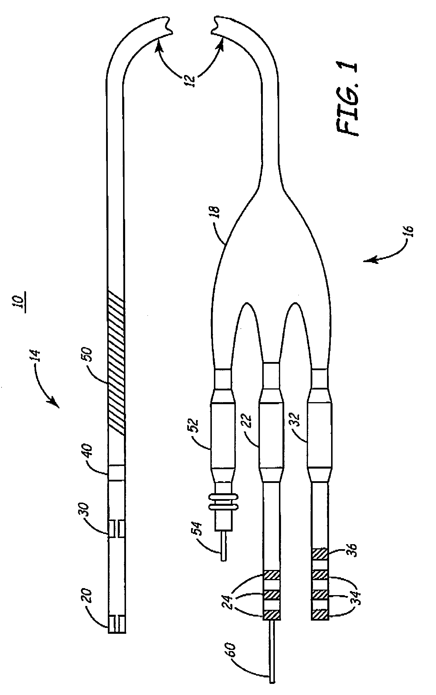
[0029]FIG. 1 is a plan view of a multipolar cardiac lead in accordance with an embodiment of the present invention. As illustrated in FIG. 1, a lead 10 according to the present invention includes an elongated lead body 12 having a connector assembly 16 at a proximal end adapted for connecting to an implantable device, such as an ICD, and an electrode head assembly 68 at a distal end 14 for carrying one or more electrodes. Lead 10 is shown having, at or near distal end 14, a tip electrode array 20, a ring electrode array 30, a ring electrode 40, and a defibrillation coil electrode 50. The tip electrode array 20 and the...


PUM


Abstract

An electrical medical lead is provided having two or more electrodes, electrically insulated from each other and electrically coupled to individually insulated filars in a multi-filar coiled conductor. When the lead is used with a medical device equipped with a switch matrix, electrodes are selected individually or simultaneously to serve as an anode or cathode in any unipolar, bipolar or multi-polar configuration for delivering stimulation and/or sensing signals in excitable tissue. In one embodiment, a tip electrode array is expandable for improving electrode contact with targeted tissue and stabilizing lead position.

Description

FIELD OF THE INVENTION[0001]The present invention relates generally to an implantable electrical stimulation and / or sensing lead, and more particularly, the present invention relates to a method and apparatus for improved stimulation and sensing of a medical electrical lead having a multiple electrode array.BACKGROUND OF THE INVENTION[0002]A wide assortment of implantable medical devices (IMDs) are presently known and in commercial use. Such devices include cardiac pacemakers, cardiac defibrillators, cardioverters, neurostimulators, and other devices for delivering electrical signals to excitable tissue and / or receiving signals from the tissue. Devices such as pacemakers, whether implantable or temporary external type devices, are part of a system for delivering an electrical therapy or monitoring a patient condition. In addition to the pacemaker device, which typically has some form of pulse generator, a pacing system includes one or more leads carrying electrodes for delivering ge...

Claims


Application Information

Patent Timeline
Patent Type & Authority Patents(United States)
IPC IPC(8): A61B5/0408A61N1/05A61N1/08A61N1/37
CPCA61B5/04085A61N1/05A61N1/056A61N1/0573A61N1/36185A61N1/3686A61N1/3704A61B5/7217A61B5/282
Inventor SOMMER, JOHN L.CHO, YONG KYUNMCCLURE, LAWRENCE C.
Owner MEDTRONIC INC
Why Eureka
Try Eureka