Apparatus, system, and method for draping annotations on to a geometric surface

a technology of geometric surfaces and annotations, applied in static indicating devices, instruments, analogue processes for specific applications, etc., can solve problems such as inability to guarantee the presence of hardware on all computers, annotations that do not appear seamless may be difficult to interpret, and annotations may become an ineffective means for conveying additional information to the viewer, etc., to achieve the effect of increasing speed and simplicity and adequate amount of fidelity

Inactive Publication Date: 2005-12-20
IBM CORP +1
View PDF17 Cites 26 Cited by
  • Summary
  • Abstract
  • Description
  • Claims
  • Application Information

AI Technical Summary

Benefits of technology

[0011]An object of this invention is an improved system and method for draping with an adequate amount of fidelity and with greater speed and simplicity.
[0012]An object of this invention is an i

Problems solved by technology

Texture mapping requires specialized graphics hardware for adequate performance during viewing, and that hardware is not currently guaranteed to be present on all computers.
When multiple images are used to represent the annotations of the model at the same time, differences in rendering parameters between images may result in a discontinuity where the images border each other and this discontinuity can stand out as a disturbing artifact.
Annotations that do not appear seamless may be hard to interpret because the eye is drawn to the abrupt changes in surface

Method used


Image

  • Apparatus, system, and method for draping annotations on to a geometric surface
  • Apparatus, system, and method for draping annotations on to a geometric surface
  • Apparatus, system, and method for draping annotations on to a geometric surface

Examples


Embodiment Construction

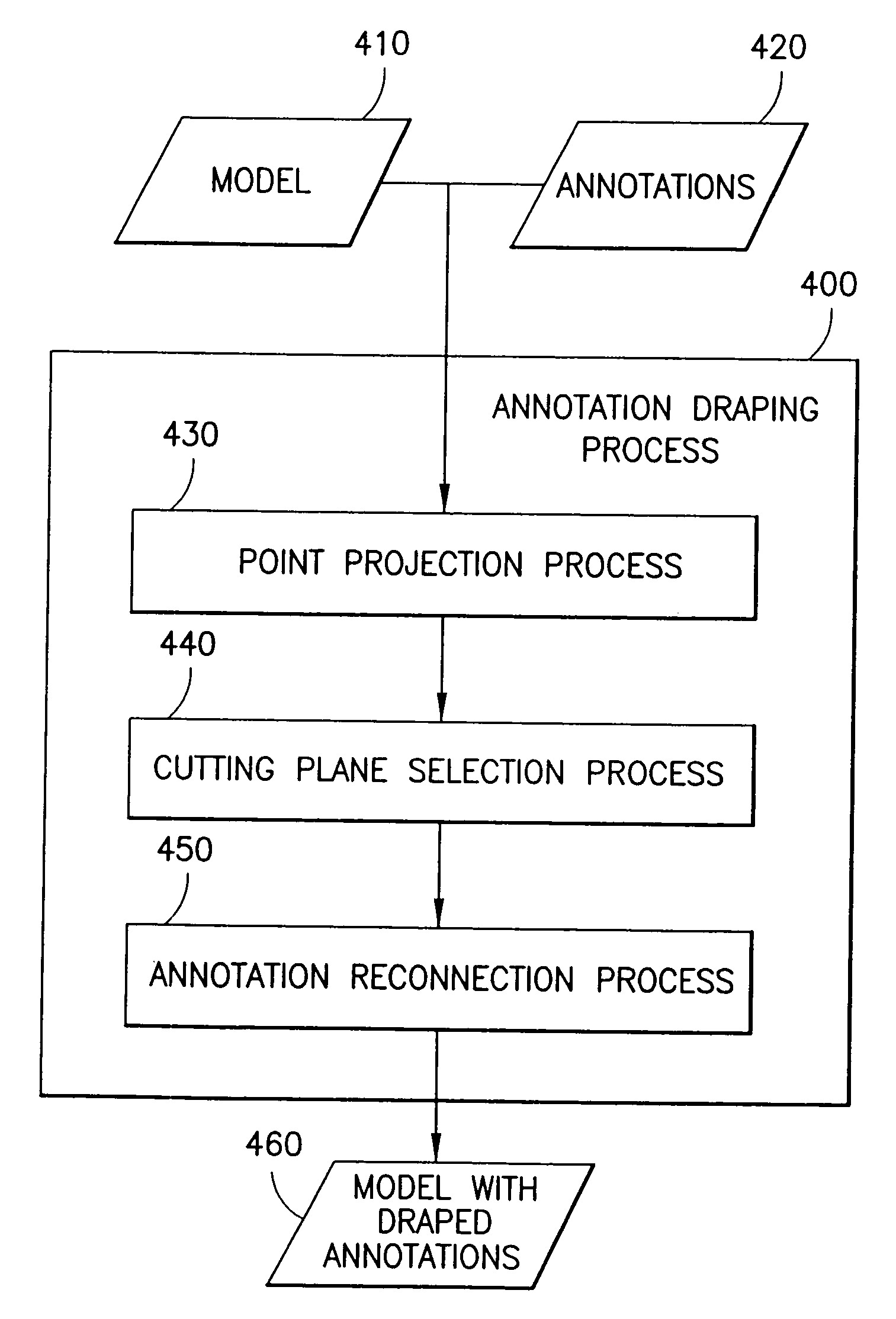
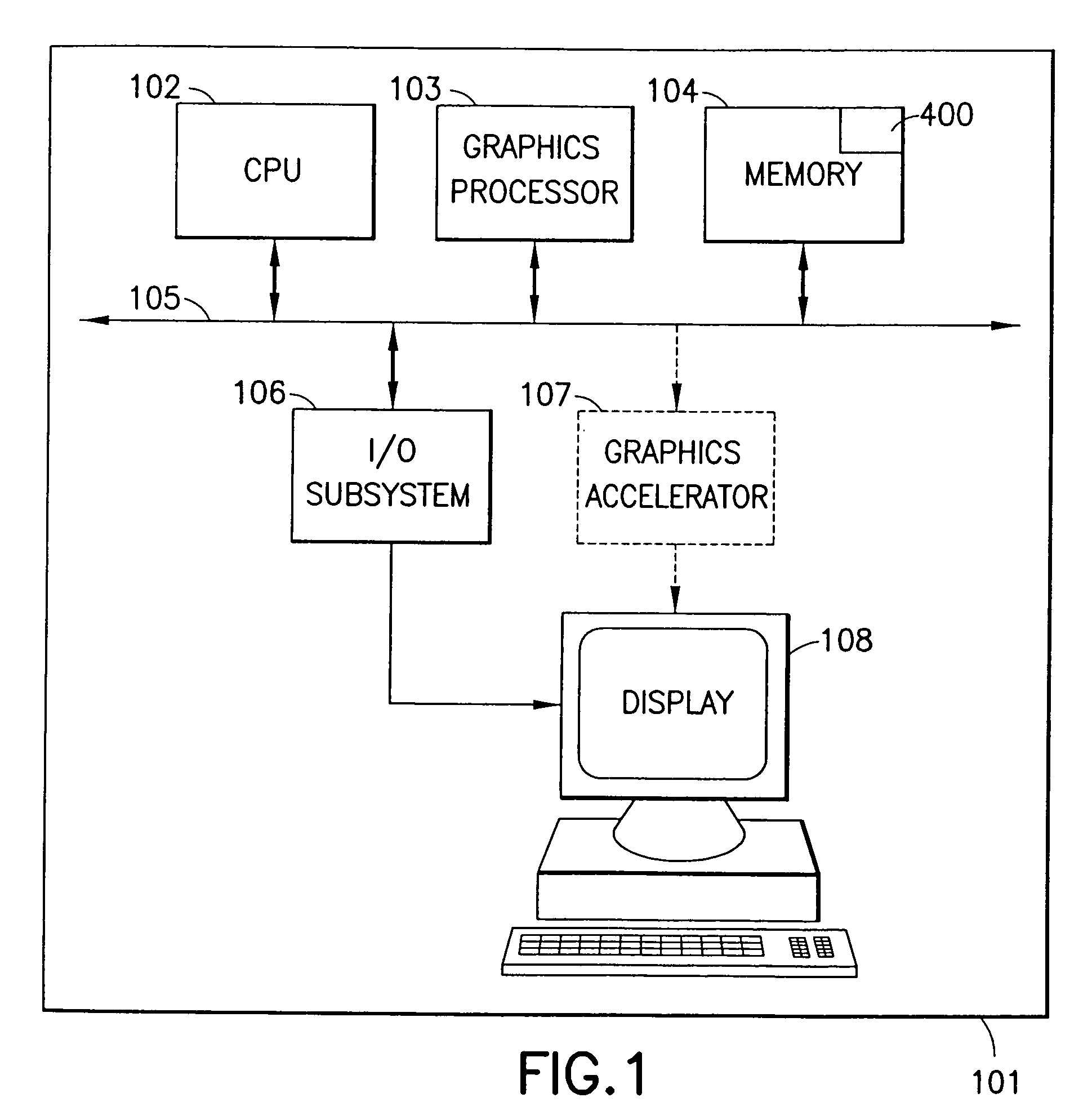
[0028]Referring now to the drawings, and more particularly, FIG. 1 is a block diagram of a preferred embodiment geometric modeling system 101 that includes a memory 104 where one or a plurality of geometric models are stored. One or more Central Processing Units (CPU) 102 access the model via the internal bus 105 and assist a graphics processor 103 in rendering the image and conveying it via the I / O subsystem 106 and the graphics accelerator 107 to the display 108. Optionally, the internal bus 105 may be connected to a network interface to transmit the geometric models across a network to remote modeling systems. These components are all well-known. A novel annotation draping process 400, described in more detail in FIG. 4, is executed by one or more of the CPUs.

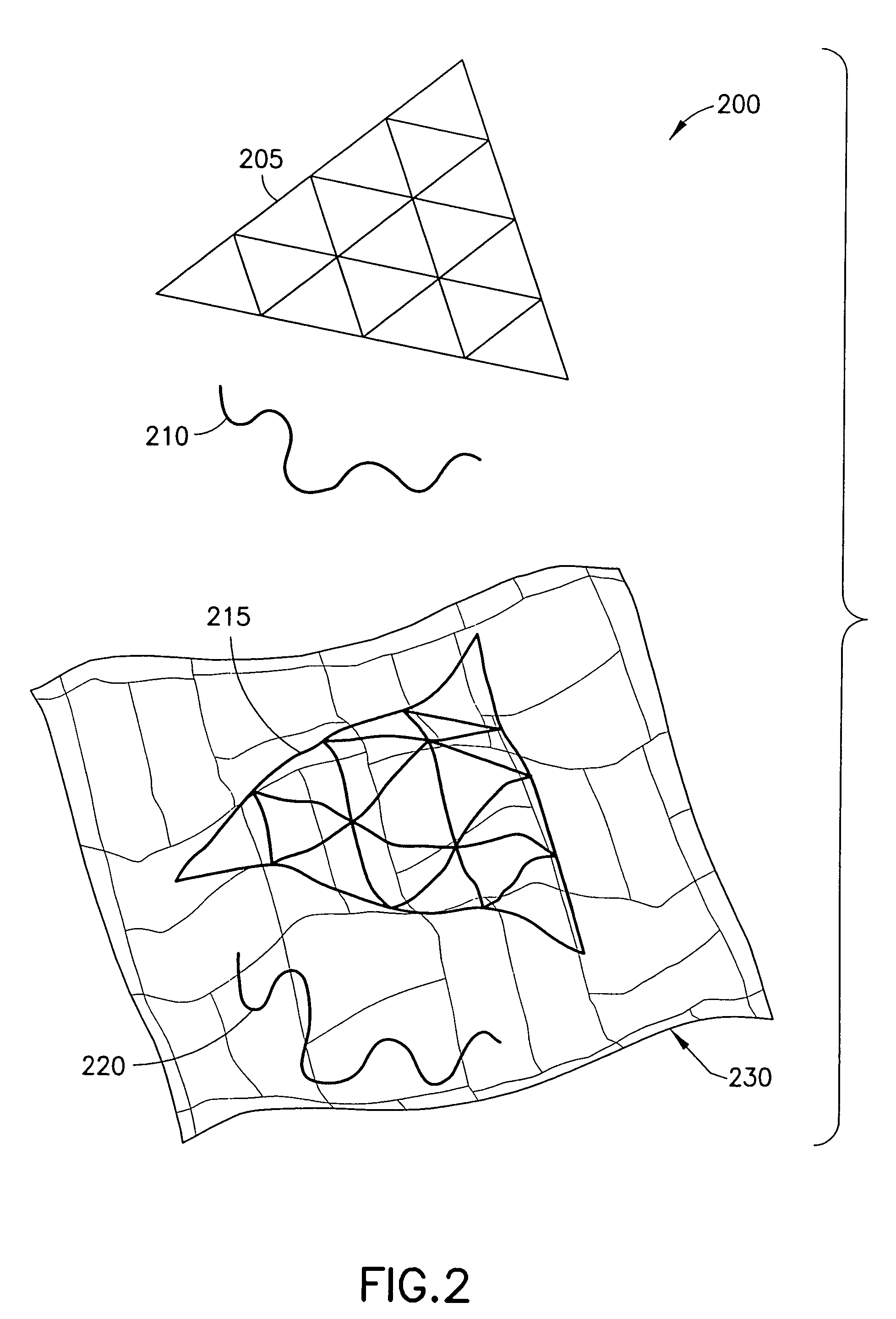
[0029]FIG. 2 shows an example 200 of annotations draped onto the surface of a model 230. The geometry of the model defines the actual shape of the surface. In this example, the geometry represents an undulating surface. The ...


PUM


Abstract

Vertices of an annotation are projected onto a surface of a (2D or 3D) model and reconnected to preserve the original appearance of the annotation. The result of our method is a new set of geometry for the annotation that geometrically conforms to the surface of the model. A plane is defined by the midpoint of the original line segment and the two projected vertices. This plane is used to create the new line segments that conform to the surface, e.g. by doing a “surface walk” between the projected points along the line defined by the intersection of the plane and the surface.

Description

RELATED APPLICATIONS[0001]This application is also related to U.S. patent application Ser. No. 09 / 686,720 entitled “System and Method for Coordinated Simplification of Surface and Wire-frame Descriptions of a Geometric Model” to Horn, et al., now U.S. Pat. No. 6,570,568 and to U.S. patent application Ser. No. 09 / 686,643 entitled “Apparatus, System, and Method for Simplifying Annotations on a Geometric Surface” to Suits, et al., now U.S. Pat. No. 6,518,964, both of which are assigned to the assignees hereof, filed on the same day as this disclosure and are herein incorporated by reference in their entirety.BACKGROUND OF THE INVENTION[0002]In CAD / CAM (Computer Aided Design / Computer Aided Manufacturing) and many other industries, one needs to view and interact with three-dimensional (3D) models obtained from a local machine or a remote server. These 3D models contain both geometry and surface features. The geometry of a model defines its shape, typically as a set of vertices and their ...

Claims


Application Information

Patent Timeline
IPC IPC(8): G06T15/00G06T15/04G06T19/00G09G5/36
CPCG06T17/20G06T19/00G06T2210/21G06T2219/004G06T2219/008
Inventor KLOSOWSKI, JAMES T.SUITS, FRANKHORN, WILLIAM P.LECINA, GERARD
Owner IBM CORP
Why Eureka
Try Eureka