Speech coding apparatus and speech decoding apparatus

a speech coding and speech technology, applied in the field of speech coding apparatus and speech decoding apparatus, can solve the problems of large calculation amount, large calculation amount, and disadvantageous conventional coding schemes, and achieve the effect of small calculation amount and suppression of deterioration in sound quality

Inactive Publication Date: 2005-12-20
NEC CORP
View PDF19 Cites 13 Cited by
  • Summary
  • Abstract
  • Description
  • Claims
  • Application Information

AI Technical Summary

Benefits of technology

[0016]The present invention has been made in consideration of the above situation in the prior art, and has as its object to provide a speech coding system whi...

Problems solved by technology

The conventional coding scheme described above is disadvantageous in that a large calculation amount is required to select an optimum sound source code vector from a sound source codebook.
In this manner, the conventional coding scheme is disadvantageous in that it requires a very large calculation size.
Another problem is that at a bit rate less than 8 kb/s, especially when background noise is superimposed on speech, the background n...

Method used


Image

  • Speech coding apparatus and speech decoding apparatus
  • Speech coding apparatus and speech decoding apparatus
  • Speech coding apparatus and speech decoding apparatus

Examples


first embodiment

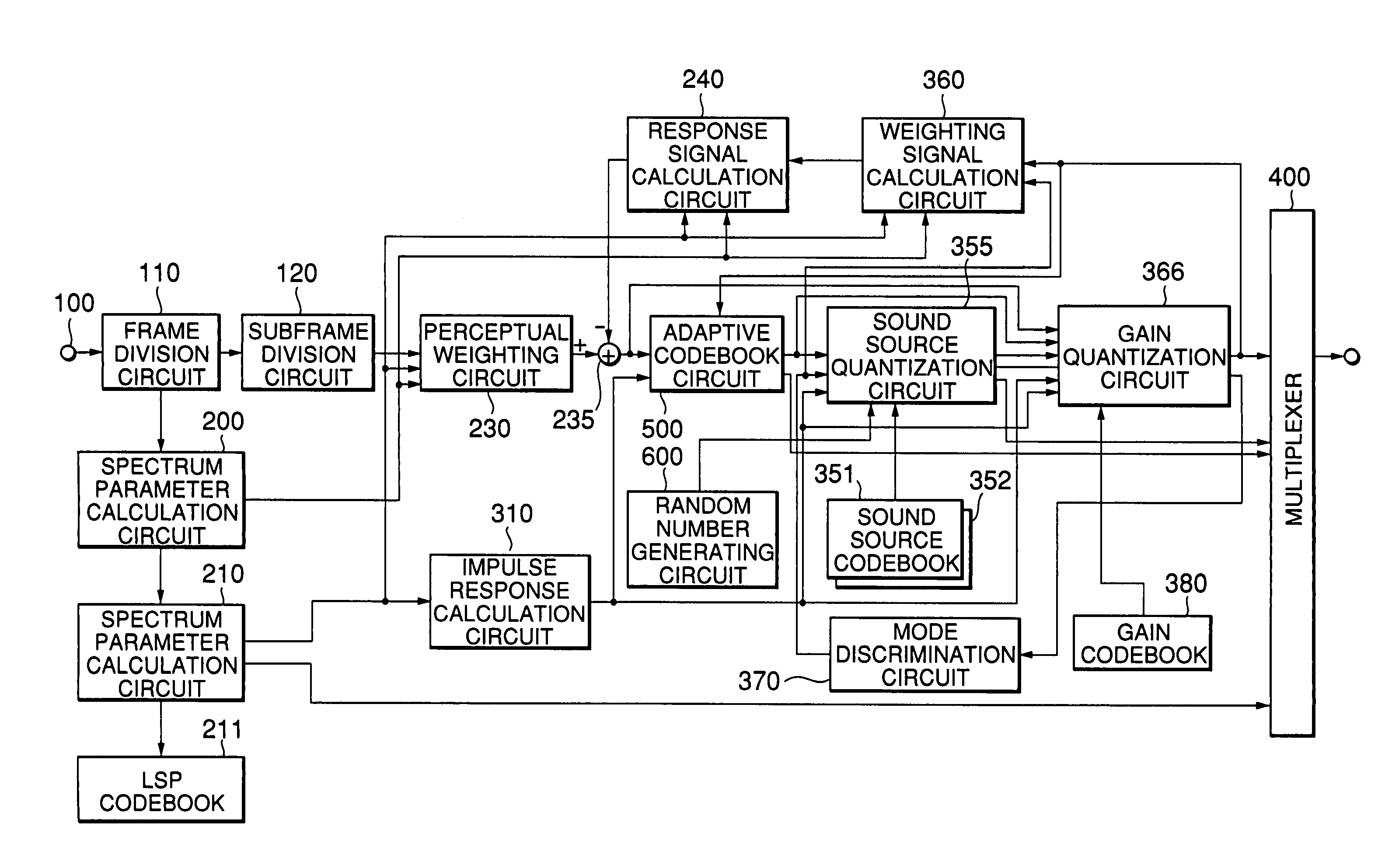
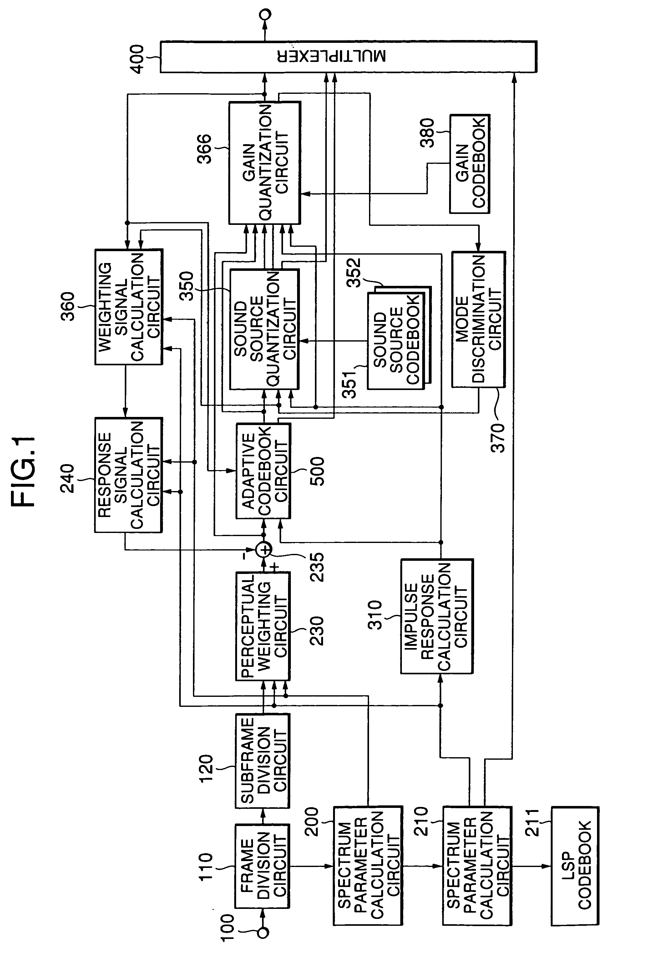
[0034]FIG. 1 is a block diagram showing the arrangement of a speech coding apparatus according to an embodiment of the present invention.

[0035]Referring to FIG. 1, when a speech signal is input through an input terminal 100, a frame division circuit 110 divides the speech signal into frames (for example, of 20 ms). A subframe division circuit 120 divides the speech signal of each frame into subframes (for example, of 5 ms) shorter than the frames.

[0036]A spectrum parameter calculation circuit 200 extracts speech from the speech signal of at least one subframe using a window (for example, of 24 ms) longer than the subframe length and calculates spectrum parameters by computations of a predetermined order (for example, P=10). In this case, for the calculation of spectrum parameters, an LPC analysis, a Burg analysis, and the like which are well known in the art can be used. In this case, the Burg analysis is used. Since the Burg analysis is disclosed in detail in Nakamizo, “Signal Anal...

second embodiment

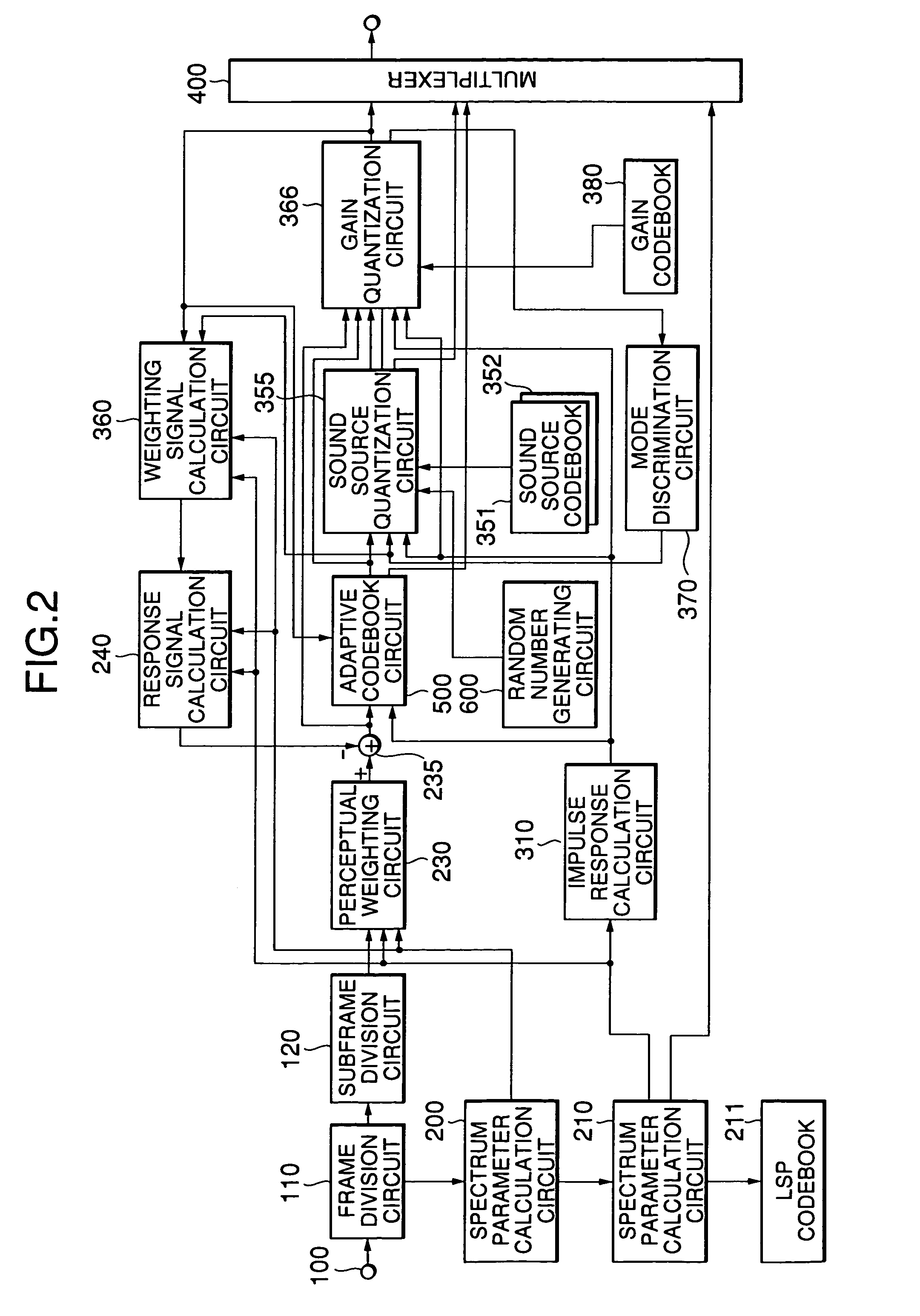
[0078]FIG. 2 is a block diagram showing the schematic arrangement of the second embodiment of the present invention.

[0079]Referring to FIG. 2, the second embodiment of the present invention differs from the above embodiment in the operation of a sound source quantization circuit 355. More specifically, when voiced / unvoiced discrimination information indicates an unvoiced sound, the positions that are generated in advance in accordance with a predetermined rule are used as pulse positions.

[0080]For example, a random number generating circuit 600 is used to generate a predetermined number of (e.g., M1) pulse positions. That is, the M1 values generated by the random number generating circuit 600 are used as pulse positions. The M1 positions generated in this manner are output to the sound source quantization circuit 355.

[0081]If the discrimination information indicates a voiced sound, the sound source quantization circuit 355 operates in the same manner as the sound source quantization...

third embodiment

[0082]FIG. 3 is a block diagram showing the arrangement of the third embodiment of the present invention.

[0083]Referring to FIG. 3, in the third embodiment of the present invention, when voiced / unvoiced discrimination information indicates an unvoiced sound, a sound source quantization circuit 356 calculates the distortions given by equations (21) below in correspondence with all the combinations of all the code vectors in a sound source codebook 352 and the shift amounts of pulse positions, selects a plurality of combinations in the order which minimizes the distortions given by: Dk,j=∑n=0N-1⁢⁢[ew⁢⁢(n)-∑i=1M⁢⁢gik′⁢⁢hw⁢⁢(n-mi-δ⁢⁢(j))]2(21)

and outputs them to a gain quantization circuit 366.

[0084]The gain quantization circuit 366 quantizes gains for a plurality of sets of outputs from the sound source quantization circuit 356 by using a gain codebook 380, and selects a combination of a shift amount, sound source code vector, and gain code vector which minimizes distortions given by: ...


PUM


Abstract

A speech coding apparatus includes a spectrum parameter calculation section, an adaptive codebook section, a sound source quantization section, a discrimination section, and a multiplexer section. The spectrum parameter calculation section receives a speech signal and quantizes a spectrum parameter. The adaptive codebook section obtains a delay and a gain from a past quantized sound source signal using an adaptive codebook, and obtains a residue by predicting a speech signal. The sound source quantization section quantizes a sound source signal using the spectrum parameter. The discrimination section discriminates the mode. The sound source quantization section has a codebook for representing a sound source signal by a combination of non-zero pulses and collectively quantizing amplitudes or polarities of the pulses in a predetermined mode, and searches combinations of code vectors and shift amounts used to shift the positions of the pulses to output a combination of a code vector and shift amount which minimizes distortion relative to input speech. The multiplexer section outputs a combination of outputs from the spectrum parameter calculation section, the adaptive codebook section, and the sound source quantization section.

Description

BACKGROUND OF THE INVENTION[0001]1. Field of the Invention[0002]The present invention relates to a speech coding apparatus and speech decoding apparatus and, more particularly, to a speech coding apparatus for coding a speech signal at a low bit rate with high quality.[0003]2. Description of the Prior Art[0004]As a conventional method of coding a speech signal with high efficiency, CELP (Code Excited Linear Predictive Coding) is known, which is disclosed, for example, in M. Schroeder and B. Atal, “Code-excited linear prediction: High quality speech at low bit rates”, Proc. ICASSP, 1985, pp. 937–940 (reference 1) and Kleijn et al., “Improved speech quality and efficient vector quantization in SELP”, Proc. ICASSP, 1988, pp. 155–158 (reference 2).[0005]In this CELP coding scheme, on the transmission side, spectrum parameters representing a spectrum characteristic of a speech signal are extracted from the speech signal for each frame (for example, 20 ms) using linear predictive coding (...

Claims


Application Information

Patent Timeline
IPC IPC(8): G10L19/08G10L19/10G10L19/12G10L19/22H03M7/30
CPCG10L19/012G10L19/10
Inventor OZAWA, KAZUNORI
Owner NEC CORP
Why Eureka
Try Eureka