Well screen assembly and system with controllable variable flow area and method of using same for oil well fluid production

a technology of oil well fluid and variable flow area, which is applied in the direction of well accessories, drilling pipes, boreholes/wells, etc., can solve the problems of reducing the requirement of flapper valves to control fluid loss, and the inability to control the flow rate of production fluid, etc., to achieve the effect of reducing production flow area and large flow area

Inactive Publication Date: 2005-12-27
HALLIBURTON ENERGY SERVICES INC
View PDF164 Cites 71 Cited by
  • Summary
  • Abstract
  • Description
  • Claims
  • Application Information

AI Technical Summary

Benefits of technology

[0011]An advantage of the present invention is the ability to vary the amount of fluid flow through a well screen assembly by changing the flow area of the well screen assembly from a maximum flow area to zero flow area.
[0012]Another advantage of the present invention is that it allows for a relatively large flow area as compared to prior art well screens.
[0013]Another advantage of the present invention is that it allows for the shutting off of water producing zones. Water producing zones can be shut off by decreasing or closing the flow area in the disclosed screens adjacent to the water producing zones, while keeping open the flow area of the disclosed screens adjacent to the non-water (or low-water) producing zones.
[0014]Another advantage of the present invention is that it allows for the shutting off of producing zones, to thereby allow treatment of poor

Problems solved by technology

It is well known that screens are designed to surround perforated portions of the production tubing or a perforated production sub, so that fluids and gases may enter the production tubing while leaving undesirable solids, such as formation sand, in the annulus.
A disadvantage of current generation screens is the inability to control flow rate of the production fluid.
Such screens operate as static devices in that they do not allow for an increase or decrease in the fluid flow area through the screen.
A disadvantage of these screens is their relatively small flow area, which can lead to a reduced rate of production fluid flow.
Another disadvantage associated with some prior art screens is the requirement that

Method used


Image

  • Well screen assembly and system with controllable variable flow area and method of using same for oil well fluid production
  • Well screen assembly and system with controllable variable flow area and method of using same for oil well fluid production
  • Well screen assembly and system with controllable variable flow area and method of using same for oil well fluid production

Examples


Embodiment Construction

[0031]The present invention provides a well screen assembly and system with controllable variable flow area and method for using the same to control the flow of production fluid, such as crude oil, from one or more production zones underneath the earth's surface, upwards through the interior of production tubing. The present invention may also be used to limit or stop the flow of production fluid from the production tubing and back into the production zones. The disclosed invention may further be used to vary the amount of production fluid loss resulting from back-flow from the production tubing into the production zones.

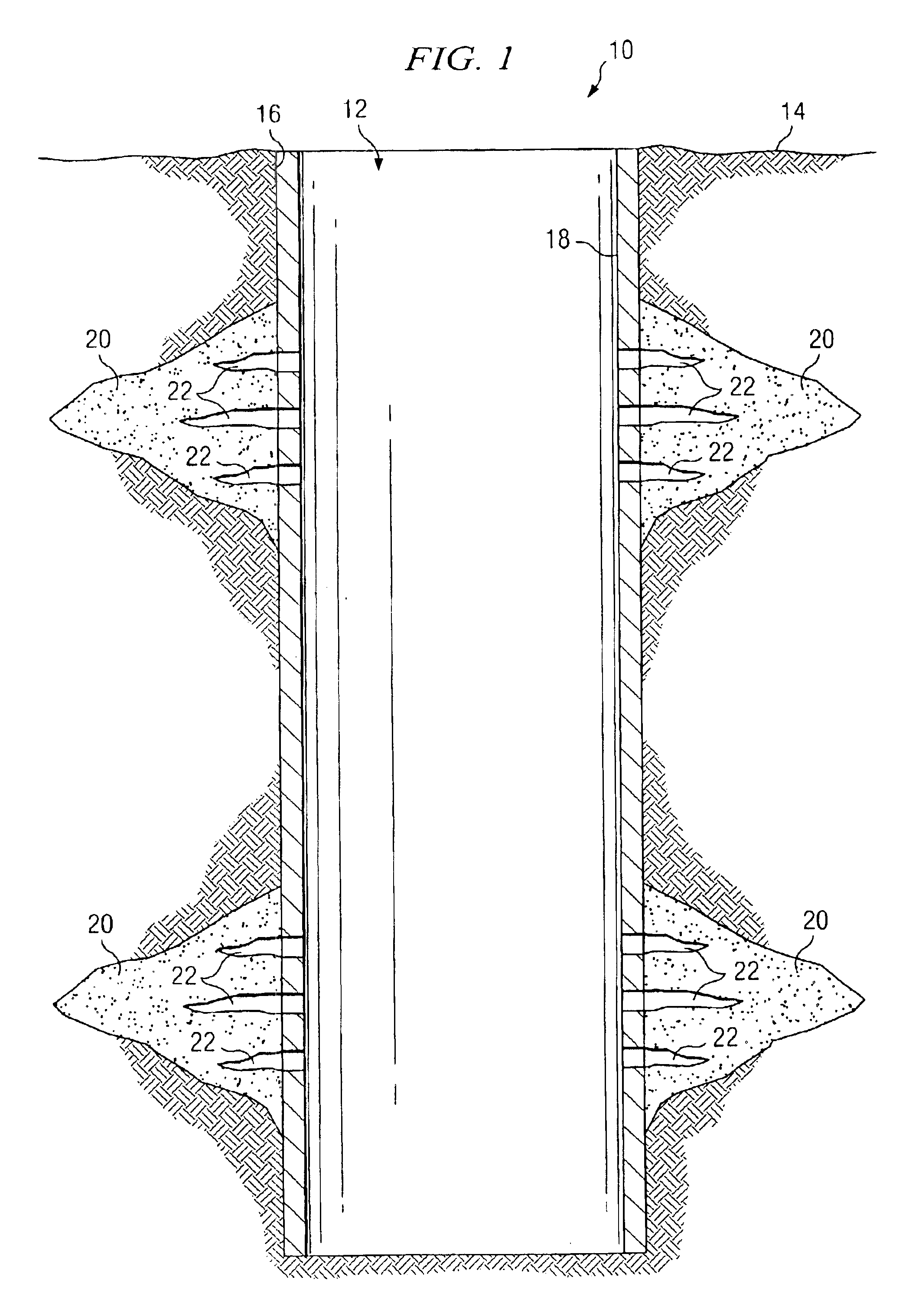
[0032]With reference now to the figures, and in particular to FIG. 1, there is shown a typical down-hole operation, denoted generally as 10, in which the present invention may be utilized. In essence, the down-hole operation 10 provides an excavation underneath the earth's surface 14 which is created using well known techniques in the energy industry. The operation ...


PUM


Abstract

A well screen assembly (70) with a controllable variable flow area. The well screen assembly (70) comprises an outer tubular section (80), the outer tubular section (80) containing a first plurality of openings (90) disposed in a pattern (100) throughout a length “L” of the outer tubular section (80); an inner tubular section (110) that is disposed within the outer tubular section (80), the inner tubular section (110) containing a second plurality of openings (120) disposed in the same pattern (100) throughout a length L of the inner tubular section (110), and when the first plurality of openings (90) and second plurality of openings (120) align, the openings form a plurality of passageways (130) through the outer tubular section (80) and inner tubular section (110). The well screen assembly (70) may therefore, vary the flow of production fluid through it and upwards through the interior of a production tubing (40).

Description

TECHNICAL FIELD[0001]The present invention relates generally to down-hole operations for oil and gas production and, more specifically, to the screening of production fluids to and from the production zones. Still more specifically, the invention relates to a system for controllably varying the flow area of a well screen assembly.BACKGROUND OF THE INVENTION[0002]Down-hole drilling and oil / gas production operations, such as those used to extract crude oil from one or more production zones in the ground, often utilize long lengths of production tubing to transmit fluids from great depths underneath the earth's surface to a well head above the surface. Such systems often use screens of various types to control the amount of particulate solids transmitted within the production fluid. It is well known that screens are designed to surround perforated portions of the production tubing or a perforated production sub, so that fluids and gases may enter the production tubing while leaving und...

Claims


Application Information

Patent Timeline
IPC IPC(8): E21B43/08E21B43/12
CPCE21B34/14E21B43/08E21B43/12E21B43/14
Inventor HENDERSON, WILLIAM D.
Owner HALLIBURTON ENERGY SERVICES INC
Why Eureka
Try Eureka