Sensorless motor driving device and its driving method

a sensorless motor and driving device technology, applied in the direction of motor/generator/converter stopper, electronic commutator, dynamo-electric converter control, etc., can solve the problems of reducing accuracy, affecting the speed and not being able to secure the non-energization period of the motor coil under the energization control, etc., to achieve prompt and reliable start of the sensorless motor and high accuracy

Active Publication Date: 2005-12-27
COLLABO INNOVATIONS INC
View PDF11 Cites 69 Cited by
  • Summary
  • Abstract
  • Description
  • Claims
  • Application Information

AI Technical Summary

Benefits of technology

[0021]An object of the present invention is to provide a sensorless motor driving device and its driving method detecting the zero crossing of BEMF with high accuracy and motor echo noises suppressed, thereby realizing the prompt and reliable start of the sensorless motor.

Problems solved by technology

In particular, the non-energization periods of the motor coils cannot be secured under the energization control similar to that of the brushless motor provided with position sensor.
Furthermore, ripples caused by the PWM control have to be reliably masked since they reduce the accuracy of the zero crossing detection.
Thus, the suppression of the motor echo noises obstructs the accurate detection of the zero crossing in the sensorless motor.
The obstruction to the accurate detection of the zero crossing obstructs improvement in the reliability of the self-commutation control, and, in particular, obstructs an increase in the torque produced in the sensorless motor.
In other words, the suppression of the motor echo noise is difficult to be compatible with the increase in the torque produced under the self-commutation control.
The obstruction to the accurate detection of the zero crossing, in addition, causes a difficulty of the prompt and reliable start of the sensorless motor as follows.
Accordingly, the angle between the magnetic pole center of the stator and the magnetic pole center of the rotor generally falls outside the optimum range, and thereby, the increase in the torque produced is generally difficult.
As a result, the start of the sensorless motor under the forced commutation control has the difficulty of increasing the starting torque, and therefore, the reduction of the starting time is difficult.
Furthermore, the starting control is susceptible to changes of load.
Stabilization of the start of the sensorless motor for any of such various loads is difficult under the forced commutation control.
Reduction of the above-described predetermined time is difficult since it impairs the reliability of the start when the accurate detection of the zero crossing is obstructed.
On the other hand, the forced commutation control has a difficulty of reducing the time required from the start of the sensorless motor until the instant when the revolving speed of the rotor attains the constant value.
Thus, the conventional sensorless motor driving device has the difficulty of a prompt and reliable switching from the forced commutation control to the self-commutation control at the start of the sensorless motor.
Therefore, a prompt and reliable start of the sensorless motor is difficult.

Method used


Image

  • Sensorless motor driving device and its driving method
  • Sensorless motor driving device and its driving method
  • Sensorless motor driving device and its driving method

Examples


embodiment 1

[0175]The switching of energization of the motor coils changes the magnetic fields through the rotor, and thereby changes the torque produced in the sensorless motor M. The change of any of the phase currents Iu, Iv, and Iw takes the shape of a trapezoid with gentle sides in the sensorless motor driving device of the present invention, as shown in FIG. 5. Accordingly, the changes in torque produced are gentle, and thereby the vibrations and motor echo noises of the sensorless motor M are suppressed enough.

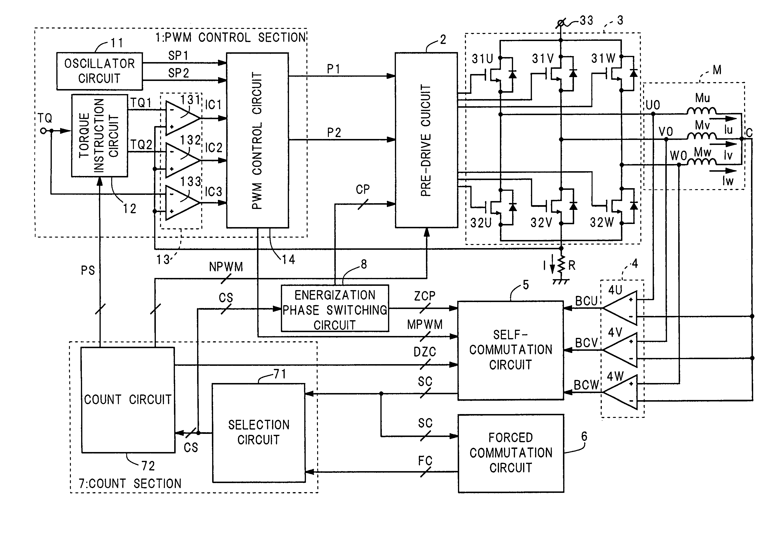
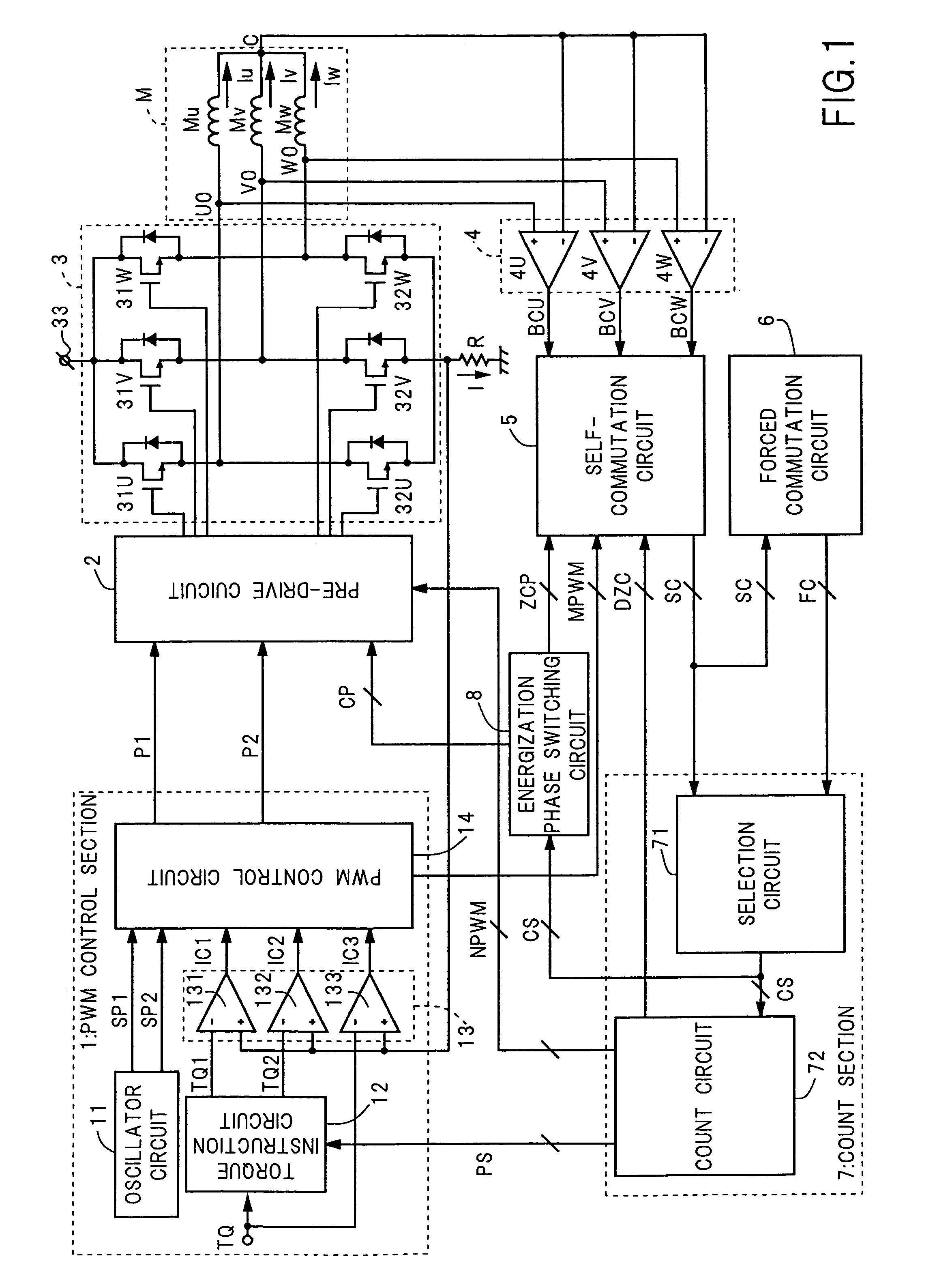
[0176]The BEMF comparing section 4 includes three comparators 4U, 4V, and 4W. See FIG. 1. The output signals BCU, BCV, and BCW of the comparators 4U, 4V, and 4W indicate the differences between the potentials of the three driving terminals U0, V0, and W0 of the sensorless motor M and the potential of the center tap C, which is hereafter referred to as a center tap voltage of motor coils.

[0177]The BEMF comparing section 4 may detect the following potential difference aside from the...

embodiment 3

[0234]The sensorless motor driving device of the present invention starts the sensorless motor M under the following forced commutation control. In particular, using the above-described forced commutation circuit 6, the driving device realizes the prompt and reliable switching from the forced commutation control to the self-commutation control, regardless of the weight of load as follows. FIG. 26 is the timing chart showing, at the start of the sensorless motor M, the forced commutation signal FC, the self-commutation signal SC, the commutation signal CS, and the phase currents Iu, Iv, and Iw. In FIG. 26, the BEMF detection periods are shown as the hatched areas.

[0235]The selection circuit 71 first selects the forced commutation signal FC as the commutation signal CS from the start instant TS of the sensorless motor M until the first detection of the zero crossing, that is, the first generation of the self-commutation signal SC at the time TC shown in FIG. 26. In that period, the f...


PUM


Abstract

A PWM control section (1) gently changes phase currents (Iu, Iv, and Iw) under a current driving control over a pre-drive circuit (2) and an output circuit (3). The pre-drive circuit (2) suspends energizing of the specific motor coil (Mu, Mv, and Mw) according to a PWM disable signal (NPWM) at PWM disable periods. A self-commutation circuit (5) performs zero crossing detection according to a BEMF detection signal (DZC) during BEMF detection periods. A count section (7) selects either a self-commutation signal (SC) or a forced commutation signal (FC) as a commutation signal (CS), whichever enters earlier, and, based on its intervals, generates the PWM disable signal (NPWM) and the BEMF detection signal (DZC). The BEMF detection period starts after the start of the PWM disable period, and finishes together with the PWM disable period at the switching of the energization phases.

Description

BACKGROUND OF THE INVENTION[0001]The present invention relates to a device and a method for driving a sensorless motor, and, in particular, those for controlling the start of a sensorless motor under a forced commutation control.[0002]In brushless motors, electric commutation is performed instead of mechanical commutation with brushes. Electric commutation requires a rotor position, in other words, a rotation angle of a rotor. Position sensors such as Hall devices are provided for conventional brushless motors, and are used to detect rotor positions. See, for example, Published Japanese patent application 2003-174789 and 2003-244983 gazettes.[0003]In a sensorless motor, a voltage is detected, which is induced in a motor coil during the rotor rotation. The voltage is hereafter referred to as a BEMF (back electromotive force). Using the BEMF, the detection of the rotor position is performed without a position sensor. Since the sensorless motor has no position sensor, its component cou...

Claims


Application Information

Patent Timeline
Patent Type & Authority Patents(United States)
IPC IPC(8): H02P3/08H02P5/00H02P6/08H02P27/08H02P6/18H02P6/20H02P7/00
CPCH02P6/182
Inventor IWANAGA, TAISHIYAMAMOTO, YASUNORINISHINO, HIDEKI
Owner COLLABO INNOVATIONS INC
Why Eureka
Try Eureka