Projecting exposure apparatus

a projecting and exposure technology, applied in the direction of photomechanical equipment, instruments, lenses, etc., can solve the problems of poor mtf performance and distortion performance, and achieve the effects of good exposure quality, distortion performance, and image forming optical system

Inactive Publication Date: 2005-12-27
FUJIFILM HLDG CORP +1
View PDF4 Cites 3 Cited by
  • Summary
  • Abstract
  • Description
  • Claims
  • Application Information

AI Technical Summary

Benefits of technology

[0017]The primary object of the present invention is to provide a projecting exposure apparatus, wherein an extinction ratio of a two-dimensional pattern of light to be projected onto a photosensitive material is capable of being enhanced, and exposure quality is thereby capable of being enhanced.
[0018]Another object of the present invention is to provide a projecting exposure apparatus, wherein adjustments for enhancing an extinction ratio of a two-dimensional pattern of light to be projected onto a photosensitive material is capable of being performed easily.

Problems solved by technology

For example, if the accuracy of the magnification of image formation is enhanced, it will occur that the MTF performance and the distortion performance become bad.
Therefore, the problems occur in that the first image forming optical system 51J cannot always be produced such that all of the characteristics described above become identical with at least the predetermined characteristics.

Method used


Image

  • Projecting exposure apparatus
  • Projecting exposure apparatus
  • Projecting exposure apparatus

Examples


Embodiment Construction

[0067]The present invention will hereinbelow be described in further detail with reference to the accompanying drawings.

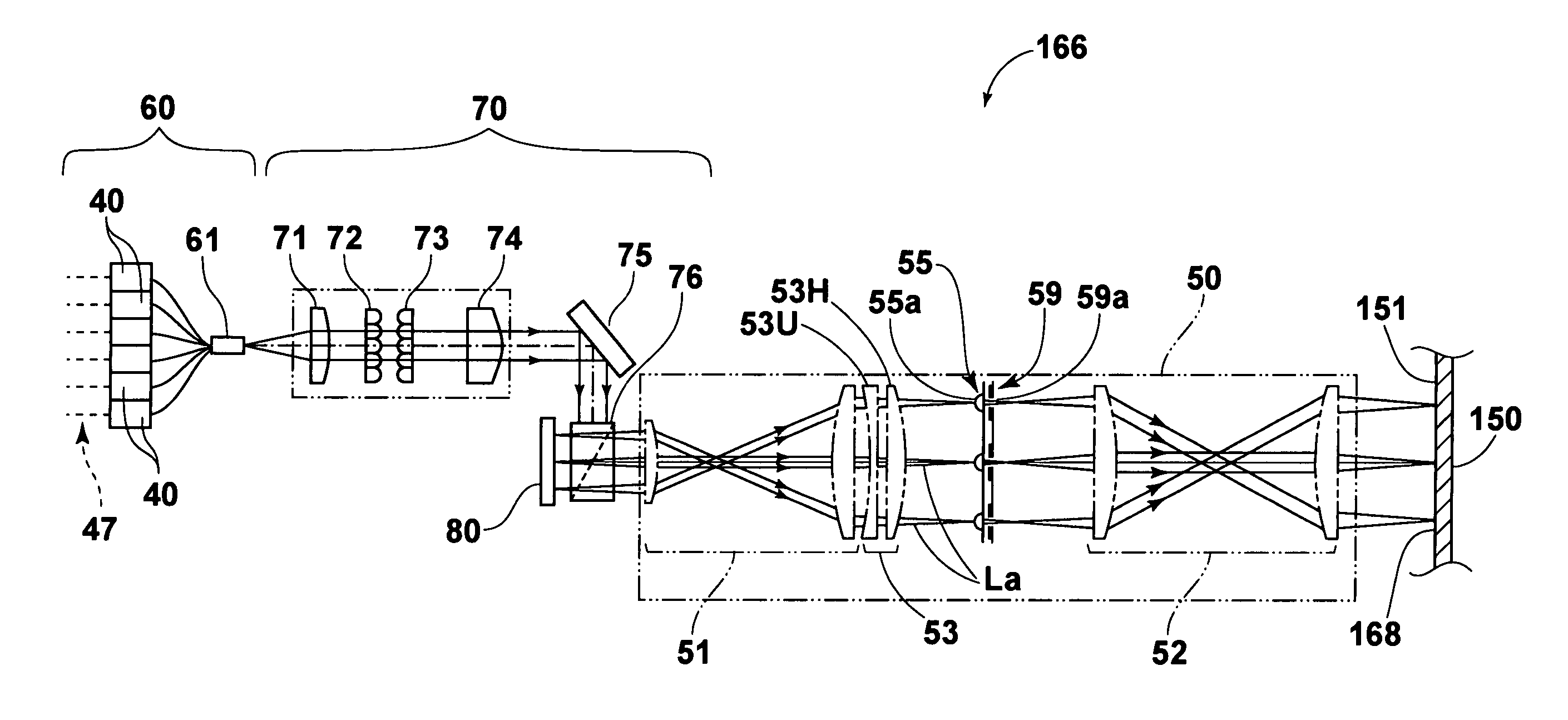
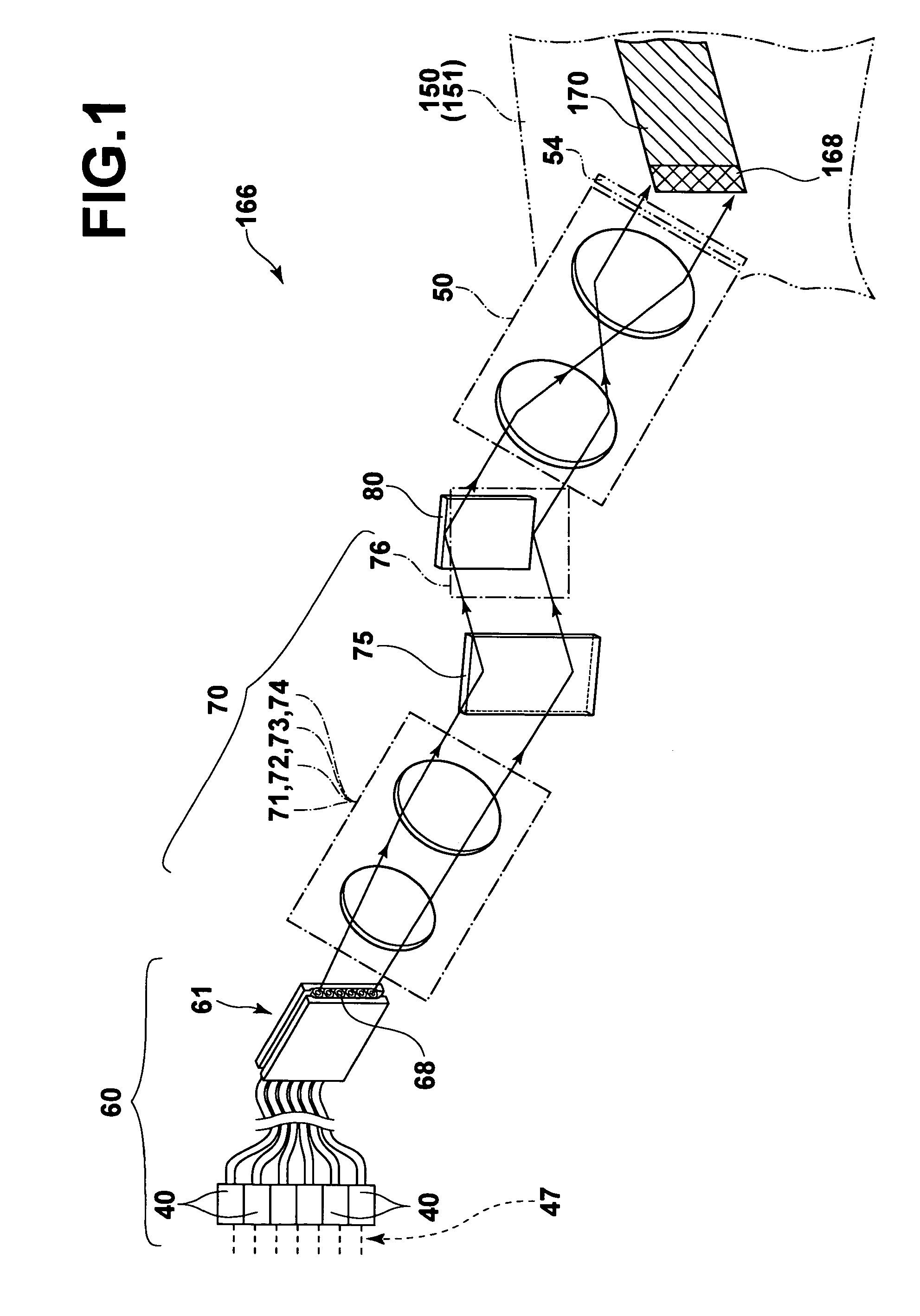
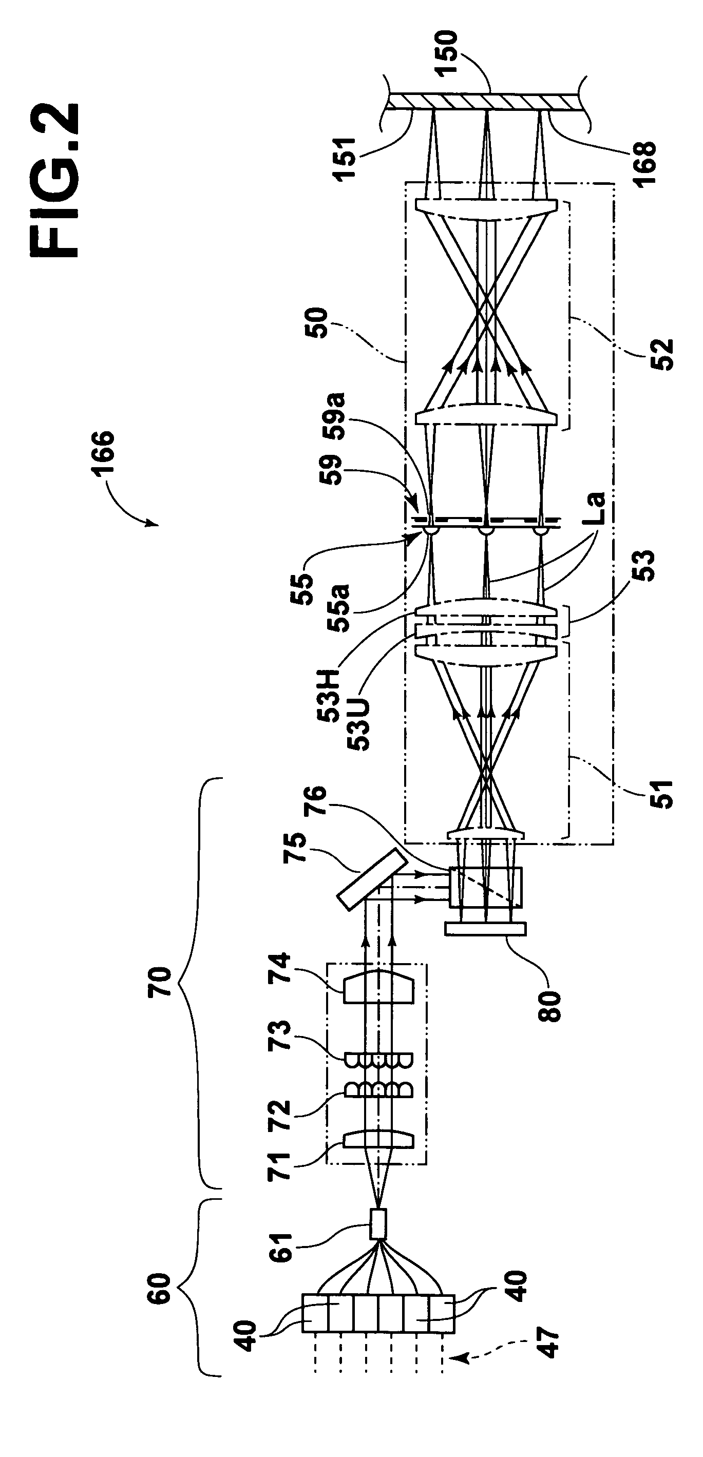
[0068]FIG. 1 is a developed conceptual view showing an exposure head of an embodiment of the projecting exposure apparatus in accordance with the present invention. FIG. 2 is a side view showing a constitution of the exposure head along optical paths of light beams traveling through the exposure head. FIG. 3 is a perspective view showing a DMD.

[0069]The embodiment of the projecting exposure apparatus in accordance with the present invention comprises a DMD 80 constituted of a plurality of micromirrors 81, 81, . . . , which are arrayed in two-dimensional directions. Each of the micromirrors 81, 81, . . . acts as one of the pixel sections for modulating incident light, which has been produced by a light source unit 60 acting as the light source and has then passed through a DMD irradiation optical system 70, in accordance with a predetermined control signal. The DMD ...


PUM

PropertyMeasurementUnit
focal lengthaaaaaaaaaa
widthaaaaaaaaaa
lengthaaaaaaaaaa

Abstract

A spatial light modulator has pixel sections for performing spatial light modulation of light. An image-side telecentric image forming optical system forms an image of a two-dimensional pattern of the light having been obtained from the spatial light modulation. A microlens array having microlenses arrayed in two-dimensional directions is located in the vicinity of a plane of image formation of the two-dimensional pattern, whose image is formed by the image forming optical system. A magnification adjusting optical system for adjusting a magnification of image formation at the time of the formation of the image of the two-dimensional pattern of the light with the image forming optical system is located between the image forming optical system and the microlens array.

Description

BACKGROUND OF THE INVENTION[0001]1. Field of the Invention[0002]This invention relates to a projecting exposure apparatus. This invention particularly relates to a projecting exposure apparatus, wherein a two-dimensional pattern of light having been obtained from spatial light modulation is projected through a telecentric image forming optical system onto a photosensitive material, and the photosensitive material is thus exposed to the two-dimensional pattern of the light.[0003]2. Description of the Related Art[0004]Projecting exposure apparatuses, wherein spatial light modulation means for performing spatial light modulation of incident light in accordance with a predetermined control signal is utilized, a two-dimensional pattern of the light, which has been obtained from the spatial light modulation performed by the spatial light modulation means, is projected onto a photosensitive material, and the photosensitive material is thus exposed to the two-dimensional pattern of the ligh...

Claims


Application Information

Patent Timeline
Patent Type & Authority Patents(United States)
IPC IPC(8): G02B13/24B41J2/45G02B26/08G03F7/20H01L21/027
CPCB41J2/451G02B26/0833G03F7/70258G03F7/70275G03F7/70291G03F7/20
Inventor ISHIKAWA, HIROMI
Owner FUJIFILM HLDG CORP
Why Eureka
Try Eureka