

Magnetic sensing element with side shield layers
a technology side shield layer, applied in the field of magnetic sensing element with side shield layer, can solve problems such as output drop, and achieve the effect of preventing side reading and minimizing the increase in the effective read track width
- Summary
- Abstract
- Description
- Claims
- Application Information
AI Technical Summary
Benefits of technology
Problems solved by technology
Method used
Image

Examples
first embodiment
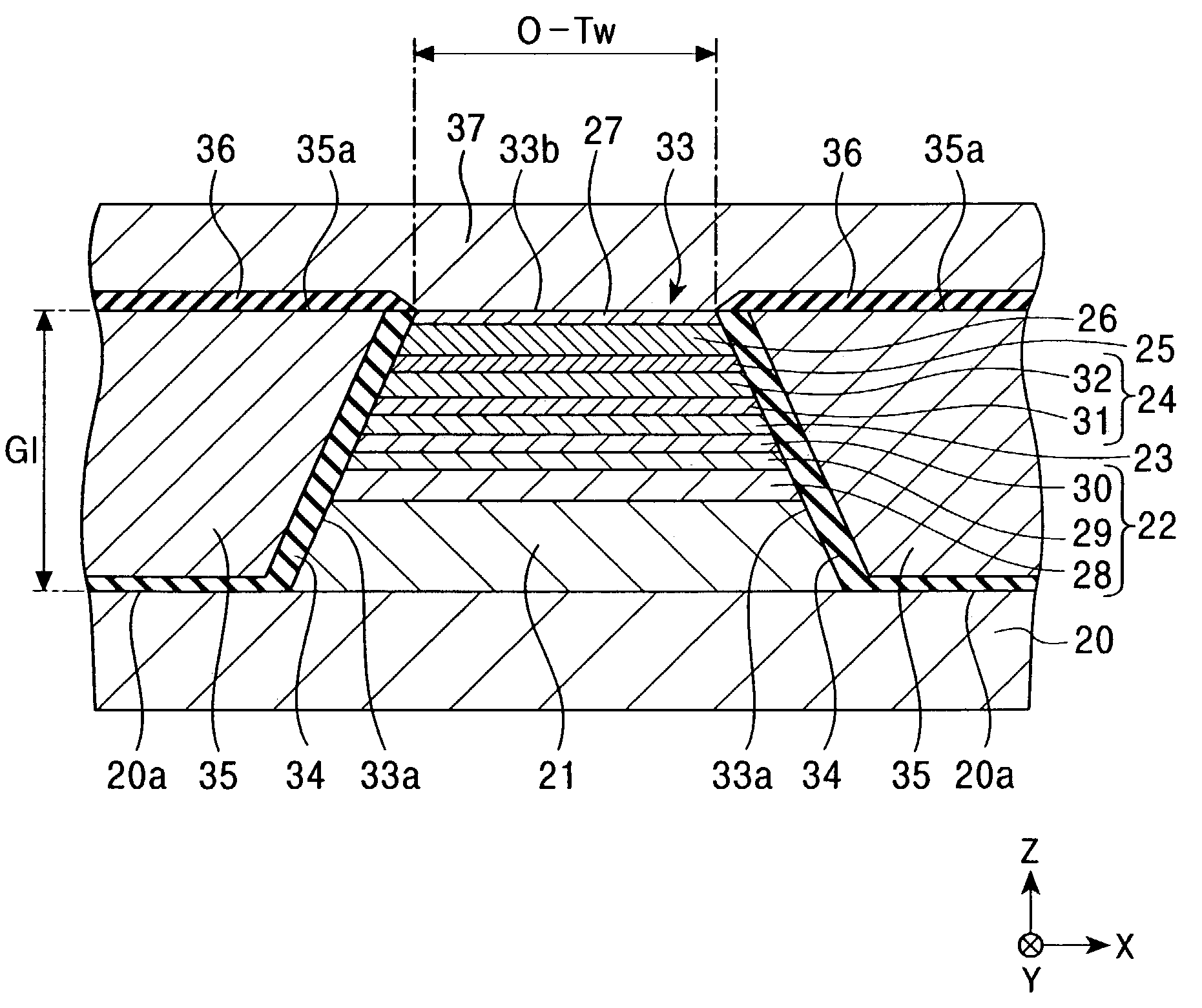
[0053]FIG. 1 is a cross-sectional view of a magnetic sensing element according to a first embodiment of the present invention viewed from a face of the magnetic sensing element that opposes a recording medium. Hereinafter, this face is referred to as the “recording-medium-opposing face” or, simply, the “opposing face”. In FIG. 1, only central part of the element extending in the X direction is shown.
[0054]The magnetic sensing element (MR head) shown in FIG. 1 is for reading an external signal recorded on a recording medium. In the present invention, an inductive write head may be stacked on the magnetic sensing element.
[0055]The magnetic sensing element is disposed on a trailing end face of a slider composed of, for example, alumina-titanium carbide (Al2O3—TiC). In order to make a magnetic head device, the slider is joined to an elastic supporting member composed of, for example, stainless steel at the opposite side of the opposing face.
[0056]Referring now to FIG. 1, a lower shield ...
second embodiment
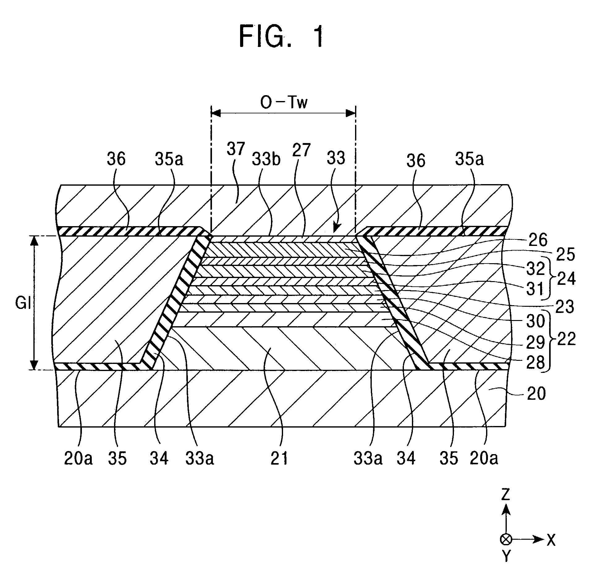
[0122]FIG. 2 is a cross-sectional view of a magnetic sensing element according to a second embodiment of the present invention viewed from the opposing face. In FIG. 2, only central part of the element extending in the X direction is shown.
[0123]The second embodiment in FIG. 2 differs from the first embodiment in FIG. 1 in that the second embodiment does not include the insulating layers 34 covering the side end faces 33a of the composite film 33 and the top face 20a of the lower shield layer 20 not overlaid by the composite film 33.
[0124]The second embodiment shown in FIG. 2 is particularly suited for use as a spin-valve GMR sensing element having the nonmagnetic material layer 23 composed of a nonmagnetic conductive material. In particular, the current flowing between the lower shield layer 20 and the upper shield layer 37 via the composite film 33 in a direction perpendicular to the surface of each layer of the composite film 33 rarely shunts into the side shield layers 35, and a...
third embodiment
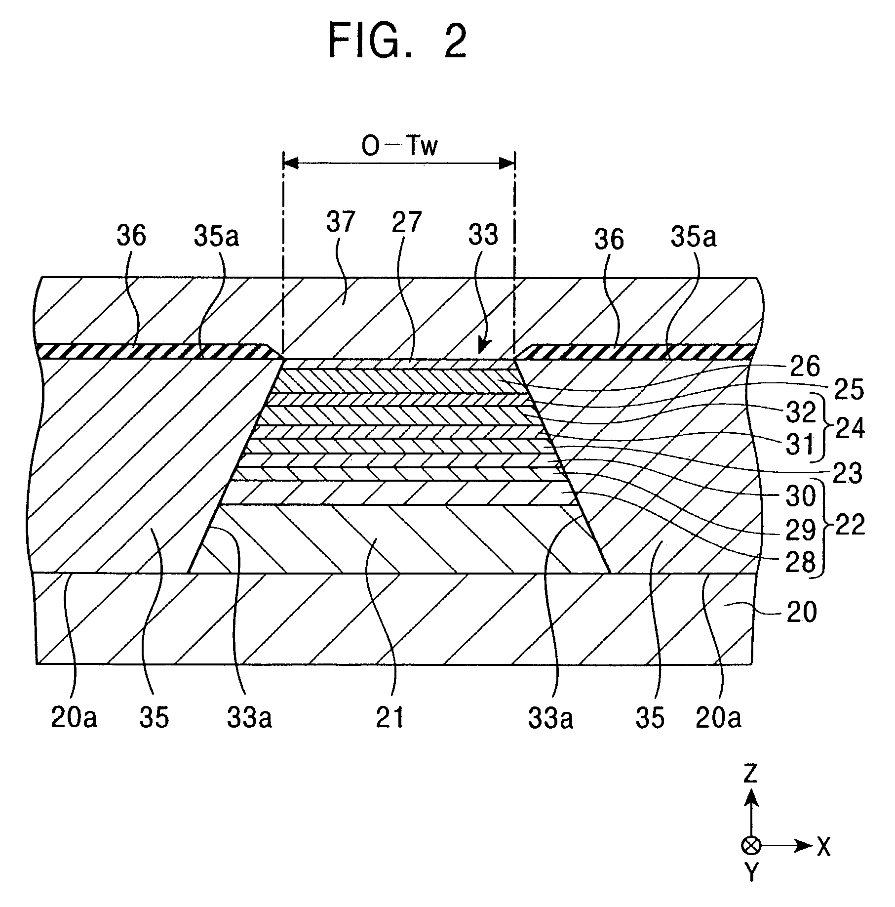
[0130]FIG. 3 is a cross-sectional view of a magnetic sensing element according to a third embodiment of the present invention viewed from the opposing face. The insulating layers 34 are formed over the top face 20a of the lower shield layer 20 not overlaid by the composite film 33. This structure prevents an electrical current flowing from the lower shield layer 20 to the composite film 33 from shunting into the side shield layers 35, thereby further increasing the output.
[0131]Alternatively, the insulating layer may be formed only between the lower shield layer 20 and the side shield layers 35 and not between the upper shield layer 37 and the side shield layers 35.
[0132]Alternatively, no insulating layer may be formed between the lower shield layer 20 and the side shield layers 35 and between the upper shield layer 37 and the side shield layers 35.
PUM
| Property | Measurement | Unit |
|---|---|---|
| thickness | aaaaa | aaaaa |
| thickness | aaaaa | aaaaa |
| width | aaaaa | aaaaa |
Abstract
Description
Claims
Application Information