Apparatus for controlling run of a car, and car using the apparatus

a technology for controlling run and car, which is applied in the direction of mechanical control devices, process and machine control, instruments, etc., can solve problems such as burden on the driver, and achieve the effect of stable braking for

Inactive Publication Date: 2005-12-27
HITACHI LTD
View PDF18 Cites 6 Cited by
  • Summary
  • Abstract
  • Description
  • Claims
  • Application Information

AI Technical Summary

Benefits of technology

[0013]Further, the present invention is characterized by an apparatus for controlling run of a car comprising a first pedal; a second pedal; a footrest apparatus for realizing a footrest function in the first pedal; and a control unit for executing control of a one-pedal mode which controls both of a braking force and a driving force of the car corresponding to an operating amount or an operating force of the first pedal, wherein a means for realizing the footrest function in the footrest apparatus comprises a mechanical stopper mechanism. The mechanical stopper mechanism has an advantage that the footrest apparatus can be constructed with a simple structure even if the other kind of energy such as electric power is difficult to be obtained.
[0031]Thereby, the braking force of the main braking means can be appropriately generated based on the temperature of the friction member of the main braking means, and accordingly a stable braking force can be obtained irrespective of the temperature.

Problems solved by technology

Therefore, in a case of, for example, acceleration a car, the driver is required to be ready to step on the brake operating mechanism so as to rapidly decelerate the car in order to avoid danger, if necessary, while he is releasing his foot from the brake operating mechanism, which is a burden for the driver.

Method used


Image

  • Apparatus for controlling run of a car, and car using the apparatus
  • Apparatus for controlling run of a car, and car using the apparatus
  • Apparatus for controlling run of a car, and car using the apparatus

Examples


Embodiment Construction

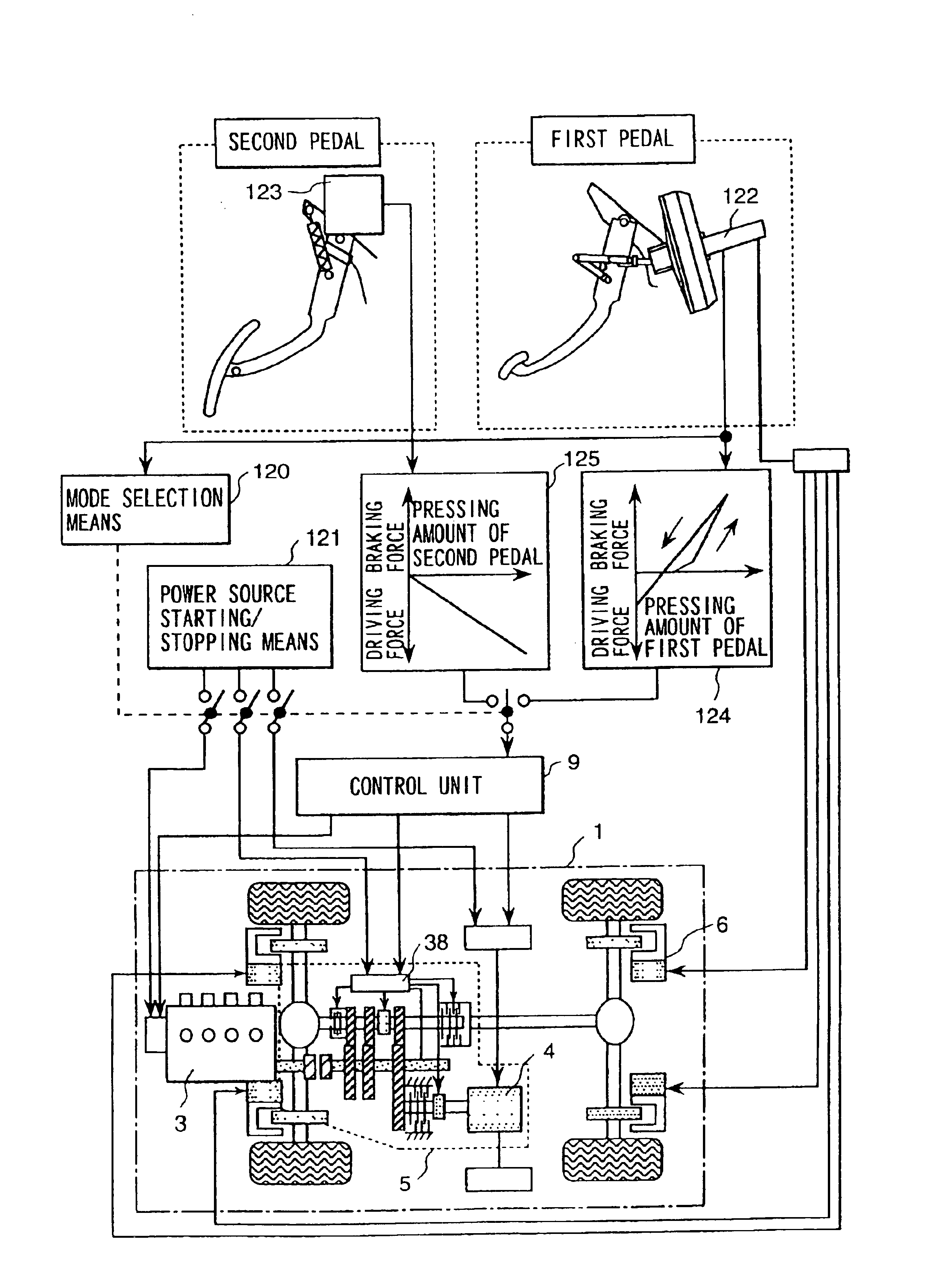
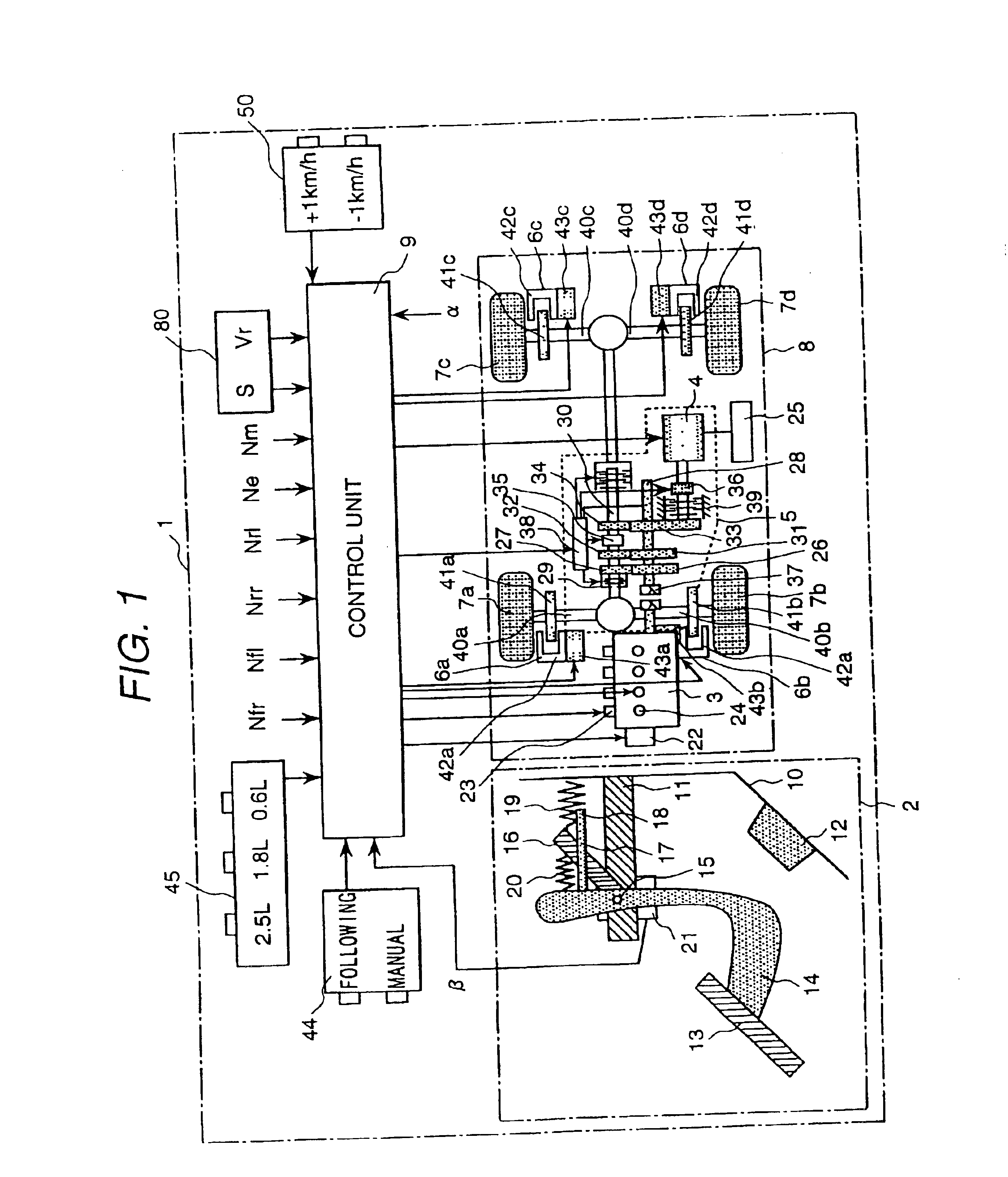
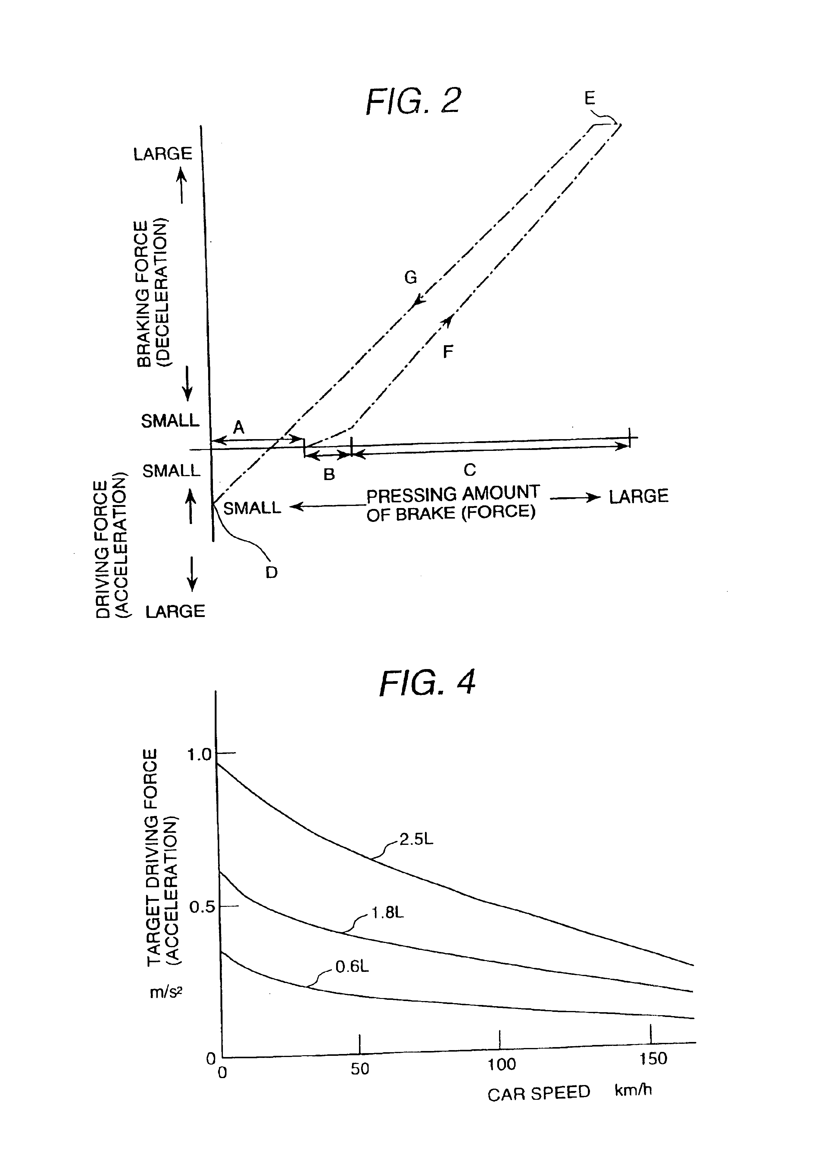
[0062]FIG. 1 is a functional block diagram showing an embodiment of a car in accordance with the present invention.

[0063]The car 1 is equipped with a braking and driving system 8 composed of a brake operating mechanism 2, an engine 3, a transmission 5 including a motor 4, brake units 6a to 6d and tires 7a to 7d; and a control unit 9 for controlling the braking and driving system 8 corresponding to input signals (to be described later).

[0064]The brake operating mechanism 2 will be described first. A support portion 11 and a stopper 12 are attached to the body 10 of the car 1. In the support portion 11 attached to the body 10, a rotary shaft 15 fixed to a first lever 14 operated by a brake pedal 13 is rotatably supported to the support portion 11. Further, a second lever 16 rotatable to the rotary shaft 15 is provided.

[0065]When the second lever 16 comes in contact with a hook 18 of a member 17 attached to the first lever 14 by operating the brake pedal 13, the second lever 16 is oper...


PUM


Abstract

In a system of accelerating a car using a brake operating mechanism, the driver is required to be ready to step on the brake operating mechanism so as to rapidly decelerate the car in order to avoid danger, if necessary, while he is releasing his foot from the brake operating mechanism, which is a burden for the driver. Therefore, a footrest function range and a braking force increasing function range are provided to an operating amount or an operating force of a pedal 13.

Description

[0001]This application is a continuation of application Ser. No. 10 / 161,610, filed Jun. 5, 2002 now U.S. Pat. No. 6,564,137, which is a divisional of Ser. No. 09 / 860,576 filed May 21, 2001 now U.S. Pat. No. 6,351,701.BACKGROUND OF THE INVENTION[0002]The present invention relates to an apparatus for controlling run of a car, a method of controlling run of a car and a car using the apparatus and, more particularly to following distance controlling auto-cruise including slow acceleration and deceleration running in a congested area. Automatic control technologies are being developed. The automatic control technologies are that a distance between a self-car and a preceding car (including an obstacle) is detected using a radar, and an engine, a motor, a transmission and a brake are automatically controlled so that the distance becomes a safe following distance. An example of the automatic control technologies is following distance controlling auto-cruise including slow acceleration and d...

Claims


Application Information

Patent Timeline
Patent Type & Authority Patents(United States)
IPC IPC(8): B60K26/00B60K26/02B60K31/00B60T7/04B60T7/22B60T8/32B60T8/58B60W10/06B60W10/10B60W10/18B60W30/16G05G5/04G06F7/00G06F13/00G06G7/00
CPCB60K26/02B60K31/042B60T7/042B60T7/22B60W10/06B60W10/11B60W10/18B60W10/184B60W30/16B60W30/17G05G5/04B60K26/00B60K2741/205B60W2540/12B60W2550/142B60W10/04B60W30/1819B60W2552/15B60W30/18159
Inventor MINOWA, TOSHIMICHIKURAGAKI, SATORUSATOU, KAZUHIKOYOSHIKAWA, TOKUJI
Owner HITACHI LTD
Why Eureka
Try Eureka