
Method for detecting a differential pressure

a technology of differential pressure and detection method, which is applied in the direction of volume measurement apparatus/methods, capacity measurement calibration, liquid/fluent solid measurement, etc., can solve the problems of complex construction and assembly of such pumps, atmospheric pressure likewise having an effect on the detection by pressure sensors, etc., and achieves the effect of simplifying the construction of the pump system

Active Publication Date: 2006-01-03
GRUNDFOS
View PDF8 Cites 62 Cited by
  • Summary
  • Abstract
  • Description
  • Claims
  • Application Information

AI Technical Summary

Benefits of technology

[0003]It is therefore the object of the invention to provide an improved method for correcting a pressure value detected in a fluid on the basis of a pressure of a surrounding medium, as well as a corresponding pump system which permit a simplified construction of the pump system.
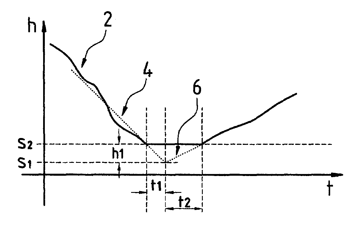
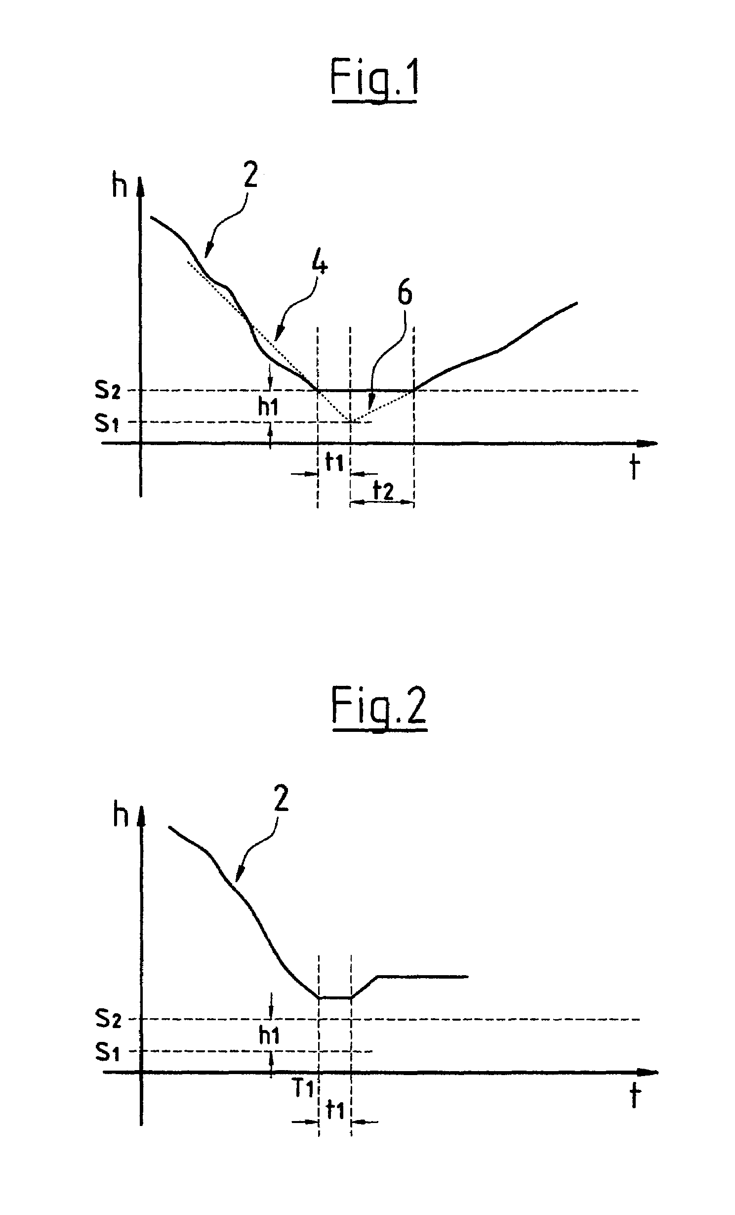
[0006]The method according to the invention serves for correcting a pressure value detected in a fluid on the basis of the pressure of a surrounding medium, wherein with this, there is formed a pressure difference between a first pressure value and a second pressure value, for example, of the surrounding medium. According to the invention at one point in time a first pressure value and at another point in time a second pressure value is detected. Subsequently the second pressure value is corrected on the basis of the first pressure value, wherein preferably a pressure difference between the two detected pressure values is evaluated. This method according to the invention thus allows a pressure sensor to detect absolute values only, but at two different points in time, in order to determine a pressure difference. Thus a differential pressure sensor which is impinged on two sides may be done away with. The method according to the invention permits the evaluation of a pressure difference with a sensor impinged on one side. This has the further advantage that in such a sensor which usually comprises a membrane, the detection electronics may be arranged on a side of the membrane which is not impinged by pressure. This simplifies the insulation or sealing of the electronics with respect to the fluid in which the pressure is to be determined. A simplified sensor construction is thus possible.
[0021]The pressure sensor is preferably arranged above the suction port of the pump. In this manner the pump is prevented from running dry whilst pumping free the pressure sensor, which would render more difficult or even prevent the starting of the pump again. It may be ensured that the suction port is constantly situated in the fluid also during the evaluation of the pressure of the surroundings, when the fluid level is lowered below the level of the pressure sensor.
[0023]It is further preferred for a control means comprising the calibration means to be arranged in a terminal box or in the pump housing or stator housing. In this manner one creates a compact pump or a compact pump unit into which all control means are integrated so that the connection and starting operation of the pump are simplified.
[0024]The pressure sensor is preferably an absolute pressure sensor impinged on one side. This permits a simple and inexpensive design of the pressure sensor. For example a membrane in the pressure sensor may be impinged from one side with pressure, whilst the required electronics for determining the deflection of the membrane may be arranged on the opposite side of the membrane protected from the fluid.

Problems solved by technology

With this however it is a problem that changes of the atmospheric pressure likewise have an effect on the detection by the pressure sensor.
This renders the construction and the assembly of such pumps quite complicated.

Method used


Image

  • Method for detecting a differential pressure
  • Method for detecting a differential pressure

Examples


Embodiment Construction

[0030]The method according to the invention and in particular the pump system according to the invention may be applied wherever a differential pressure between a fluid and a surrounding medium needs to be determined for measurement or control purposes. The method is preferably applied to a pump with which the fluid level is detected via a pressure sensor in order to switch the pump on and / or off. In order to be able to determine the exact fluid level it is necessary to determine the differential pressure between a pressure at a certain height in the fluid and the pressure of the surroundings, since otherwise fluctuations of the pressure of the surroundings would influence the determined value for the fluid or liquid level. According to the method according to the invention, for this, the pressure of the surroundings and the pressure in the fluid are not determined simultaneously but at different points in time in succession.

[0031]With a submersible pump as for example is applied fo...


PUM


Abstract

The invention relates to a method for detecting a differential pressure or for correcting a pressure value detected in the fluid on the basis of a pressure of a surrounding medium, wherein at a first point in time the pressure of the surrounding medium is detected and at a later, second point in time the pressure of the fluid is detected, and the pressure value detected in the fluid is corrected on the basis of the pressure of the surrounding medium. The invention furthermore relates to a pump system with a level sensor in which this method is applied, as well as to the use of a pressure sensor in such a pump system.

Description

BACKGROUND OF THE INVENTION[0001]The invention relates to a method for correcting a pressure value detected in a fluid on the basis of a pressure of a surrounding medium, as well as to a pump system with a level sensor and to the use of a pressure sensor in a corresponding pump system.[0002]Submersible pumps are usually equipped with a level sensor or a level switch which switches the pump on and off in dependence of the fluid level in the pump sump. With this pressure sensors may be used as level sensors which detect the fluid pressure. Since the fluid pressure changes in dependence on the height of the fluid level above the pressure sensor, by way of the fluid pressure one may determine the liquid level and accordingly switch the pump on and off. With this however it is a problem that changes of the atmospheric pressure likewise have an effect on the detection by the pressure sensor. Thus when determining the fluid level inaccuracies occur due to fluctuations in the pressure of th...

Claims


Application Information

Patent Timeline
IPC IPC(8): G01F25/00F04D15/02
CPCF04D15/0218
Inventor NYBO, PETER JUNGKLASILVES, LASSEYLI-KORPELA, HEIKKI
Owner GRUNDFOS
Learn More