In particular, when conducted in microfluidic volumes, complicated
biochemical reactions may be carried out using very small volumes of liquid.
Imprinting methods in PMMA have also been demonstrated (see, Martynova et al,
Analytical Chemistry (1997) 69: 4783-4789) However, these techniques do not lend themselves to
rapid prototyping and manufacturing flexibility.
Moreover, the tool-up costs for both of these techniques are quite high and can be cost-prohibitive.
Attempts to conduct separations or detections in microfluidic volumes have been stifled by difficulties such as making such tools in microfluidic scale and then integrating such tools into microfluidic devices.
Another difficulty is accurately measuring stoichiometric microfluidic volumes of reagents and solvents to perform analyses on a microfluidic scale.
Additionally, difficulties in rapidly prototyping microfluidic devices are compounded by attempts to incorporate multiple analytical tools.
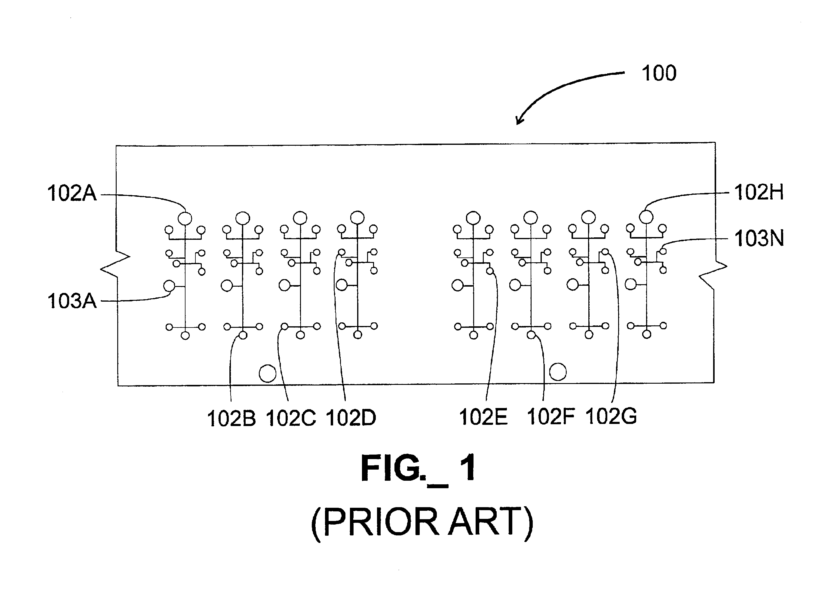
A particular challenge that has arisen in the design and fabrication of microfluidic devices is the proliferation of inputs and outputs associated with such devices.
The large number of I / O connections required by the device 100 would have a tendency to either expand the size of the device to accommodate the connections or complicate fabrication and operation of the device.
In particular, providing a large number of I / O connections in a compact area elevates the likelihood of fabrication and / or operational errors.
One consequence of this approach is that it becomes difficult, if not impossible, to substantially expand the functionality and complexity of the fluidic operations due to structural limitations.
Thus, in a two dimensional device, it is impossible to use of more than two common non-intersecting
reagent inputs when more than two functional features are used.
Likewise, the use of more than two functional features is impossible when more than two common non-intersecting inputs are used.
However, such an approach would substantially increase the manufacturing complexity of such a microfluidic device as well as compound the likelihood of component failures that could render the device inoperable.
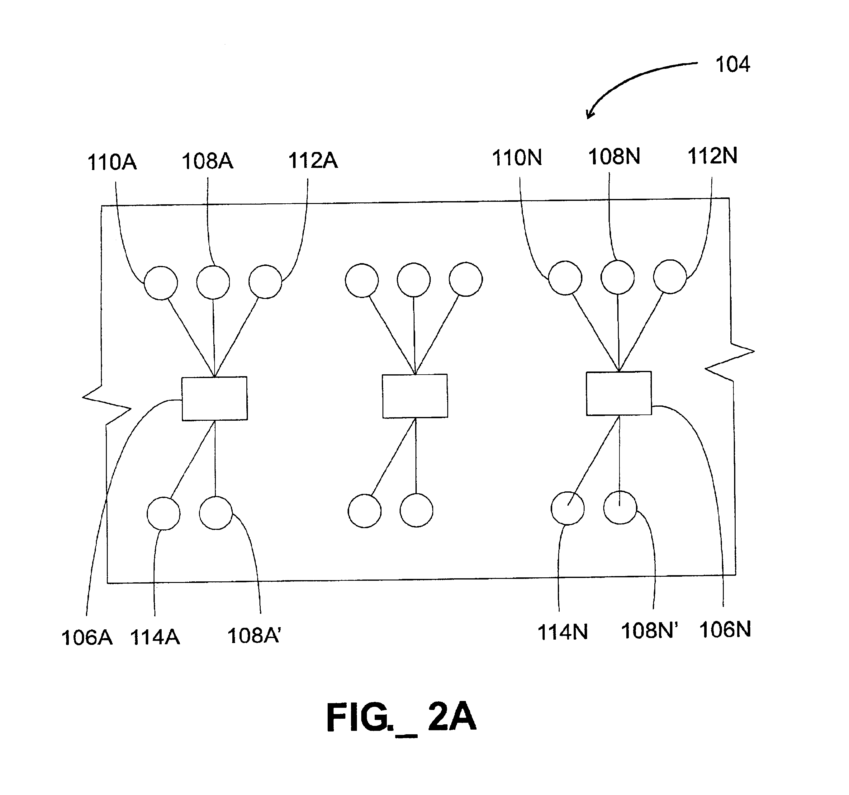
The use of common inputs, while potentially simplifying the I / O connections to a microfluidic device, also may create additional problems.
Thus, fluids in microfluidic structures often exhibit surprising and unexpected properties.
As a consequence of this behavior, it may be difficult to consistently and accurately divide and distribute a
reagent stream to a plurality of functional features, simply because it may be difficult to predict the particular flow paths that will be adopted by a given fluid flowing within a multi-path microfluidic structure.
However, as a design becomes more complex, due to, for example, increased feature density or input positions required to maintain compatibility to a particular
laboratory device, such careful positioning of reagent inputs may not be possible.
If the feature density increases substantially, however, the convolutions required to provide the desired
impedance matching may become very complex, thereby complicating the design, fabrication, operation and validation of the device.
Furthermore, any such device remains constrained by the channel intersection problem described above.
Such interface requirements tend to enlarge the
footprint of the device, complicate operation, complicate manufacture of the device and / or increase the complexity of other devices used in conjunction with the device.

