Biped locomotion robot

Inactive Publication Date: 2006-01-03
HONDA MOTOR CO LTD
View PDF13 Cites 10 Cited by
  • Summary
  • Abstract
  • Description
  • Claims
  • Application Information

AI Technical Summary

Benefits of technology

[0005]An object of the present invention is to provide a

Problems solved by technology

However, it is difficult to separate independence and subordination between the multiple variables with high precision in the development phase.
It is also difficult to describe a foot rising movement and a foot grounding movement that are associated with walking correctly.
For th

Method used


Image

  • Biped locomotion robot
  • Biped locomotion robot
  • Biped locomotion robot

Examples


Example

[0037]Hereinafter, a biped locomotion robot of the present invention will be described in detail with reference to the attached drawings.

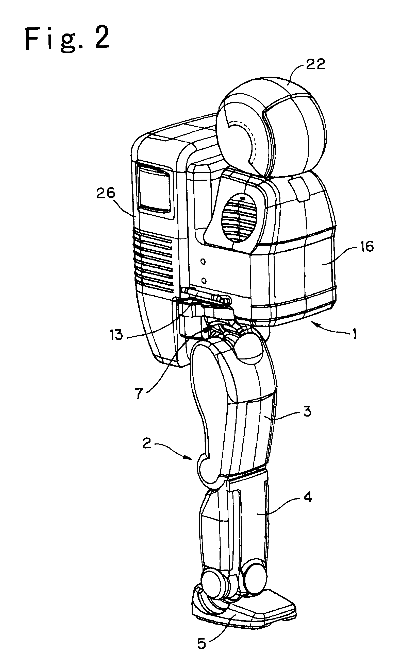
[0038]FIG. 2 is a perspective view of the biped locomotion robot according to an embodiment of the present invention. Referring to FIG. 2, the biped locomotion robot of the present invention is composed of a fundamental body portion 6, and a body section 1 and two leg portions 2 with respect to the fundamental body portion 6. A control unit 26 is provided on the rear side of the body section 1. In FIG. 2, only one leg portion is shown.

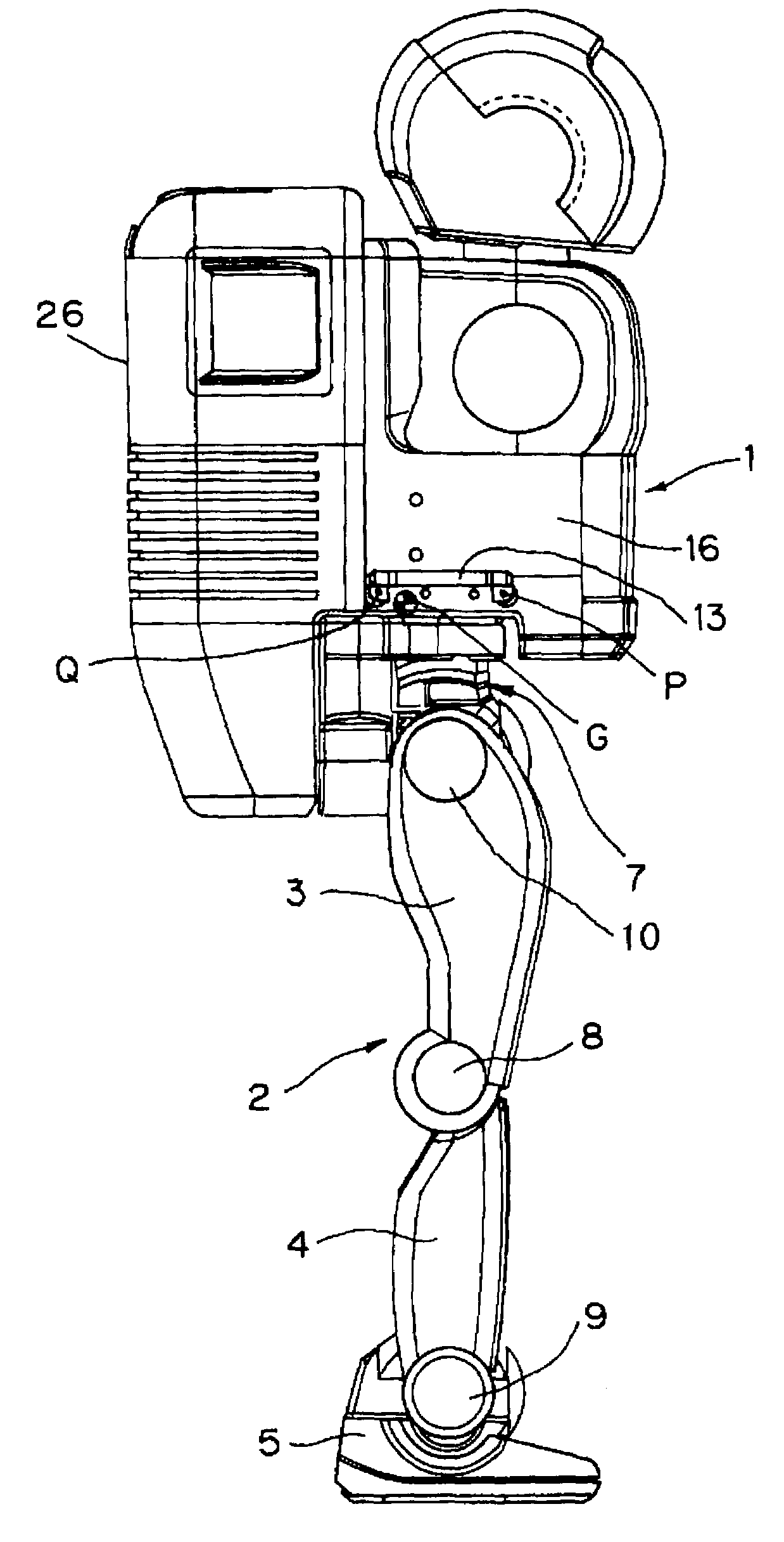
[0039]Referring to FIG. 3, the fundamental body portion 6 is a highly rigid body. The fundamental body portion 6 is supported by 2-axis rotatably by each of the leg portions 2. Each leg portion 2 is supported by 2-axis rotatably by a foot portion 5. Also, the fundamental body portion 6 is provided with two side plate sections 12 (not shown in FIG. 3) for a gap to stand up in both side ends of the fundamental body port...


PUM


Abstract

The movement analysis becomes easy and the control of all the movement systems is realized better through the initialization of the multiple coordinate systems. The fundamental body portion 6 is coupled to a foot portion 5 through a first joint portion 7, a first link 3, a second joint portion 8, a second link 4, and a third joint portion 9. The rigidity of the first link 3 is lower than that of the fundamental body portion 6, and the rigidity of the second link 4 is lower than that of the second link 4. It is possible to position the second link 4 and the foot portion 5 in a high precision to a mechanical origin which is predetermined to the fundamental body portion, for the reason of the rigidity relation. Handle portions 13 are coupled in two positions to the fundamental body portion 6. When the whole posture is initialized based on the mechanical origin, the center of gravity G of the whole robot is located between two vertical planes containing the two positions. In the initialization, a first joint portion 7, a second joint portion 8, and a third joint portion 9 are located between the two vertical planes. Thus, because the whole balance is taken, the origin adjustment is easy.

Description

TECHNICAL FIELD[0001]The present invention relates to a biped locomotion robot.BACKGROUND ART[0002]A humanoid robot, especially a biped locomotion robot, has being developed as an autonomous movement machine operable in environments where human beings have to execute difficult activities, such as care activity and in home and rescue activity in a fire scene. As shown in FIG. 1, such a robot is composed of an element system comprising a plurality of elements (head 101, body 102, and legs 103) which are under subordinative control of each other based on multiple joints, and an element relating system which relates the element system (joints 104, 105, 106, 107, 108, and 109 as 1-, 2- and 3-axis rotation systems). The whole control of the element system and the element relating system is described based on multiple variables belonging to each system and multiple parameters. However, it is difficult to separate independence and subordination between the multiple variables with high preci...

Claims


Application Information

Patent Timeline
IPC IPC(8): B25J5/00B25J9/08B62D57/032
CPCB62D57/032B25J9/08B25J5/00
Inventor TAKAHASHI, HIDEAKI
Owner HONDA MOTOR CO LTD
Why Eureka
Try Eureka