Electrical candle lamp

a candle lamp and electric technology, applied in the field of electric candles, can solve the problems of very restricted availability of a cavity inside the fixture to house the sensor, and achieve the effect of convenient assembly or replacemen

Inactive Publication Date: 2006-01-03
INT MARKETING
View PDF9 Cites 35 Cited by
  • Summary
  • Abstract
  • Description
  • Claims
  • Application Information

AI Technical Summary

Benefits of technology

[0017]Therefore, the present invention provides a new and improved electrical candle lamp provided with an ambient light sensor mounted

Problems solved by technology

In these cases, the availability of an unobtrusive cavity

Method used


Image

  • Electrical candle lamp
  • Electrical candle lamp
  • Electrical candle lamp

Examples


Embodiment Construction

[0025]The preferred embodiments of the present invention will now be described with the reference to accompanying drawings.

[0026]For purposes of the following description, the terms “upper”, “lower” and derivatives of such terms shall relate to the invention as oriented in FIG. 1 and are used for ease of explanation and are not limiting. However, it is to be understood that the invention may assume various alternative orientations, except where expressly specified to the contrary. It is also to be understood that the specific devices illustrated in the attached drawings, and described in the following specification are simply exemplary embodiments of the inventive concepts. Specific dimensions and other physical characteristics relating to the embodiments disclosed herein are not to be considered as limiting, unless expressly stated otherwise.

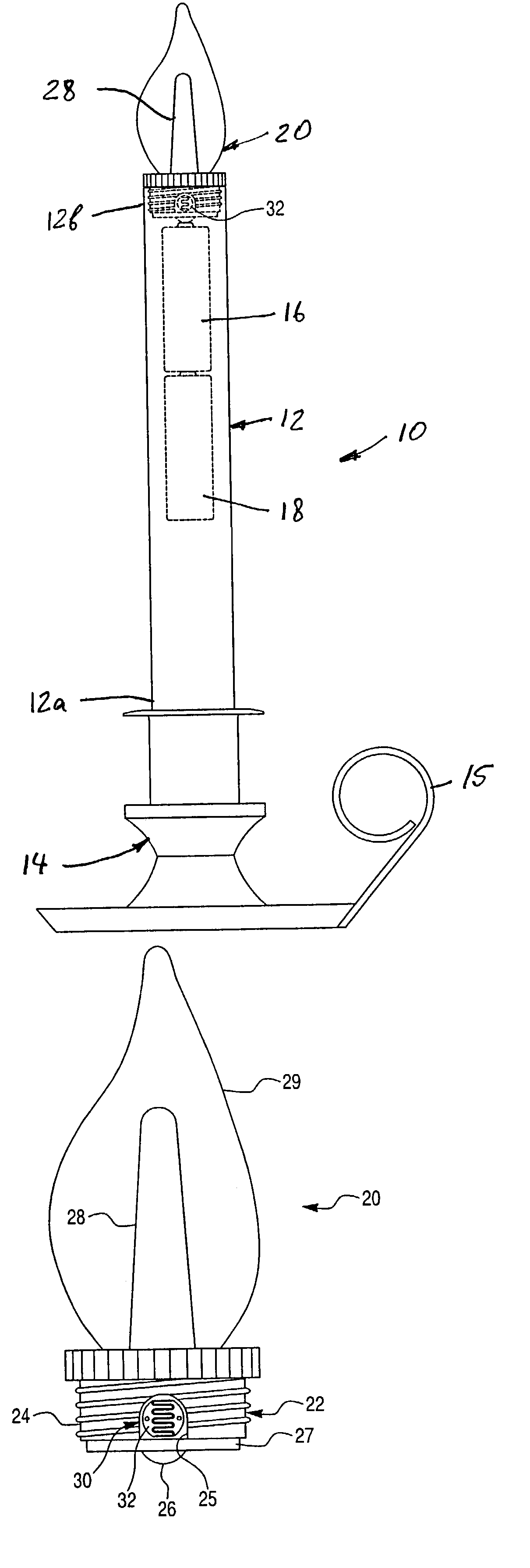
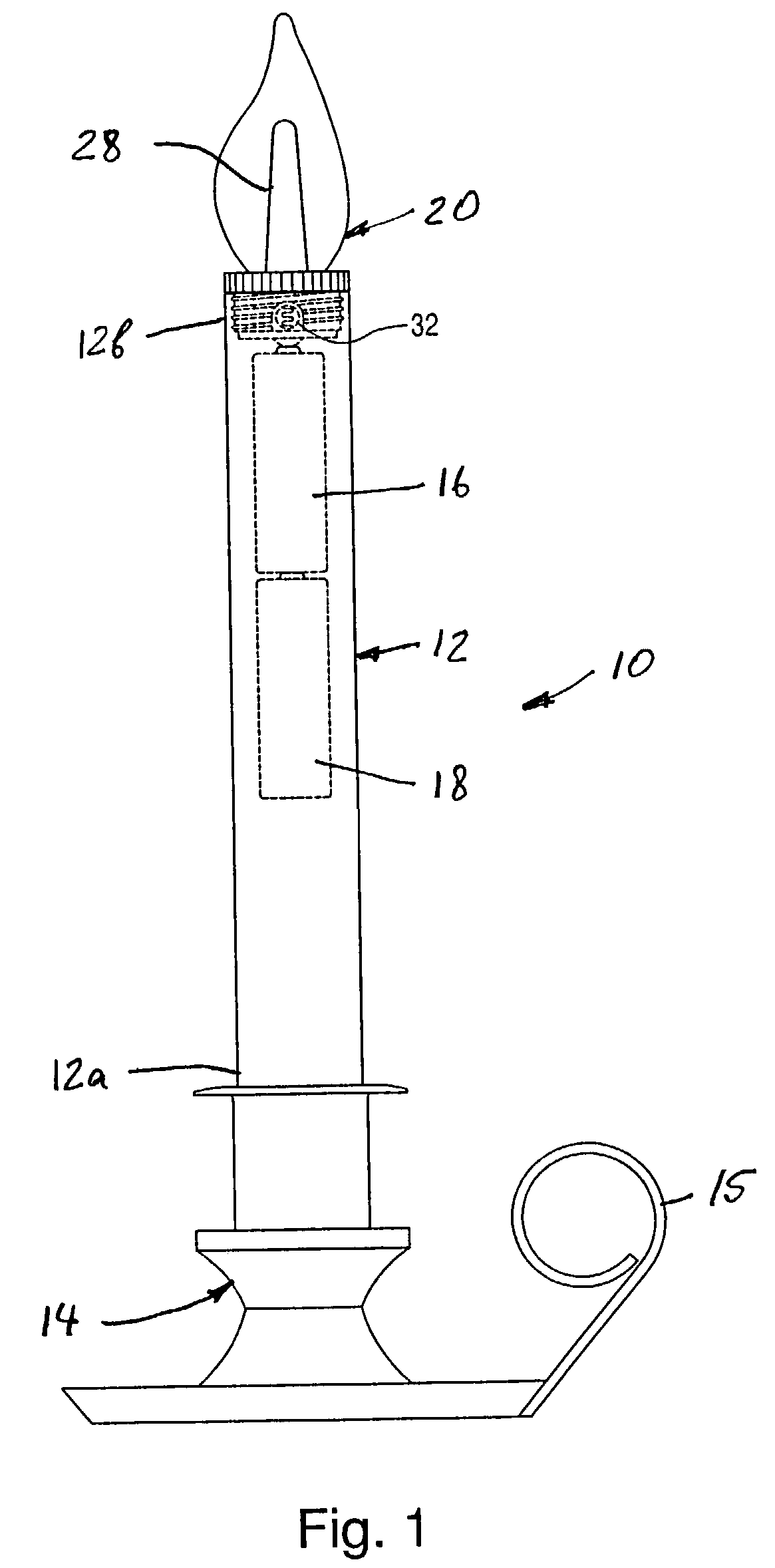
[0027]FIG. 1 of the drawings illustrates the preferred embodiment of an electric candle lamp, generally designated with the reference numeral ...


PUM


Abstract

The electrical candle lamp comprises a translucent candlestick member having a lower end and an upper end, a support member provided at the lower end of the candlestick member, and a light emitting assembly secured to the upper end of the candlestick member. The light emitting assembly includes a base portion, a light emitting device mounted to the base portion and an electronic control unit for controlling operation of the light emitting device. The electronic control unit includes an ambient light sensor provided for automatically turning the light emitting device on if ambient light level is below a predetermined level and for turning the light emitting device off if ambient light level is above the predetermined level. The ambient light sensor protrudes through an opening formed in an outer surface of the base portion of the light emitting assembly and is exposed to ambient light.

Description

BACKGROUND OF THE INVENTION[0001]1. Field of the Invention[0002]The present invention relates to an electrical lamps in general, and is more particularly directed to a self-powered electrical candle lamp including an illumination device and an electronic control unit provided with an ambient light sensor provided for automatically turning the illumination device on and off in response to an ambient light level.[0003]2. Description of the Prior Art[0004]There currently exist electrical candlestick lamps including a light bulb and standard electrical cord and plug for connection with a conventional household outlet. Typically, these electrical type candlestick lamps include a plastic base connected to a plastic candlestick provided with an electrical socket for a conventional light bulb having a threaded type electrical connector base. A length of standard two wire electrical cord extends through the base and candlestick portion to connect with the electrical socket at one end and pro...

Claims


Application Information

Patent Timeline
IPC IPC(8): F21S4/00F21S9/02F21S9/03F21S10/04F21V23/04
CPCF21S6/001F21S9/02F21S9/037F21V23/0442F21S10/04F21W2121/00F21Y2101/02F21Y2115/10
Inventor YAO, HISN-TIENCHEN, TENG-HUANGBOSCHETTO, ANDREW A.
Owner INT MARKETING
Why Eureka
Try Eureka