Jack-up apparatus for marine-based platforms

a technology of jacking apparatus and platform, which is applied in the direction of caissons, drilling pipes, scaffolds, etc., can solve the problems of high shear force, high labor intensity, and high cost of construction methods, and achieves easy and inexpensive design and scale, reliable load handling, and save millions of dollars in manufacture.

Inactive Publication Date: 2006-01-03
INGLE JAMES E
View PDF23 Cites 5 Cited by
  • Summary
  • Abstract
  • Description
  • Claims
  • Application Information

AI Technical Summary

Benefits of technology

[0009]The invention provides a new jack-up MODU and MODU jacking system that can reliably handle loads several times greater than can be currently handled, can be readily and inexpensively designed and scaled for different jack-up loads, and can save millions of dollars in the manufacture of a single jack-up MODU.
[0010]In one aspect of the invention, a plurality of MODU-carried continuous linear motion motors are engaged with a plurality of MODU supporting legs to provide relative motion between the MODU platform and its supporting legs, and to also maintain the MODU platform and MODU supporting legs locked in a stationary relationship. As used herein, the term “continuous linear motion motor,” refers to a plurality of hydraulic piston / cylinder units N whose piston operations are phased so that N−1 of the plurality of piston / cylinder units are engaged with a MODU-supporting leg and providing relative motion while one of the piston / cylinder units is disengaged from the MODU-supporting leg and being repositioned for re-engagement with the supporting leg to continue the relative motion. The invention thus permits a MODU platform to be automatically jacked up hydraulically with continuous motion, avoiding the excess forces needed to overcome static friction and to accelerate the heavy masses of the MODU.

Problems solved by technology

This method of construction was labor-intensive, slow, and expensive.
Because the spur gears rotationally engage the toothed racks of the leg chords in raising and lowering the MODU supporting legs with respect to the MODU platform, the spur gear teeth and the teeth of the leg chord racks have cycloidal cross sections, and the spur gear drives are each engaged with the leg chord racks by line contact between a single tooth of the spur gear and a single mating tooth of a toothed rack, exposing the teeth of both the spur gear and the rack to extremely high shear forces and requiring that the spur gears and the toothed rack be made of an expensive high-grade steel, with a modulus of elasticity, for example, of 100,000 pounds per square inch (100 KSI).
In such systems, the plural spur gear drives are mounted vertically in sets of three units, one above another, so their pinion gears can engage the toothed racks that comprise the leg chords; however, the load is unequally shared by the plurality of engaged pinion gears, the lowest pinion gear and its engaged rack tooth carrying a significantly disproportionate portion of the load.
Because the tooth loading in current spur gear driven jack-up MODUs is approaching the stress and fatigue limits of the available materials, complex controls for the electric motors of the spur gear drives have been developed in an effort to equalize the loads that are borne by the plurality of engaged gears and the associated stresses and fatigue.
Further, during operation of the spur gear drives, grease must be mopped onto the rack teeth by the MODU crew to reduce the friction between the pinion gears and the leg chord racks, and the grease inevitably falls into the sea.
In addition to requiring expensive controls, materials and manufacturing procedures, spur gear-driven jack-up MODUs also require expensive separate locking apparatus for each supporting leg to maintain the MODU platform in a stationary position with respect to its supporting legs
The jacking systems of jack-up MODUs are currently expensive to design and manufacture and are not expected to satisfy future requirements.
The ability to meet this demand has, however, approached its practical limit with existing materials and technology, and a new jack-up MODU and MODU jacking system are needed.

Method used


Image

  • Jack-up apparatus for marine-based platforms
  • Jack-up apparatus for marine-based platforms
  • Jack-up apparatus for marine-based platforms

Examples


Embodiment Construction

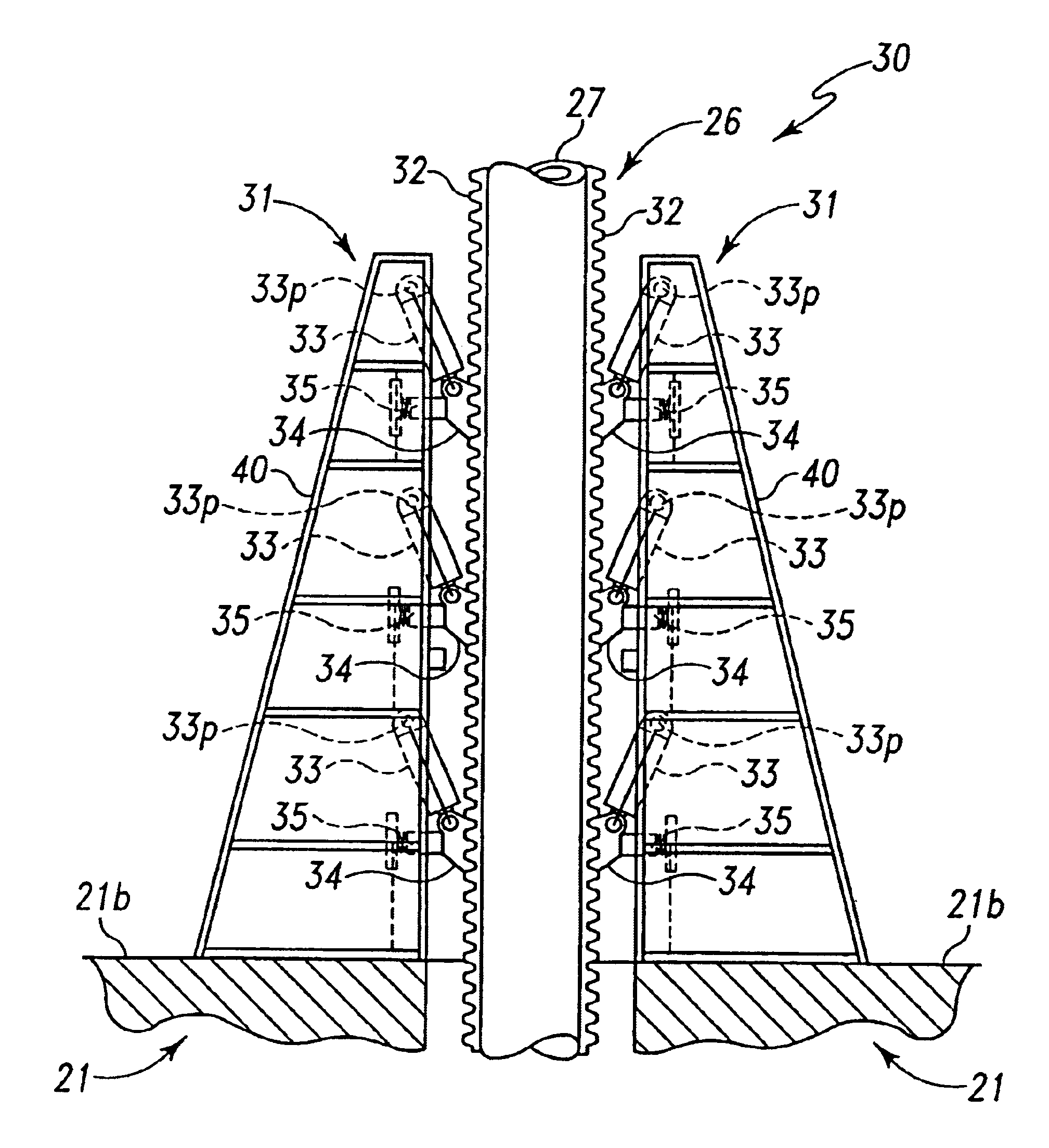
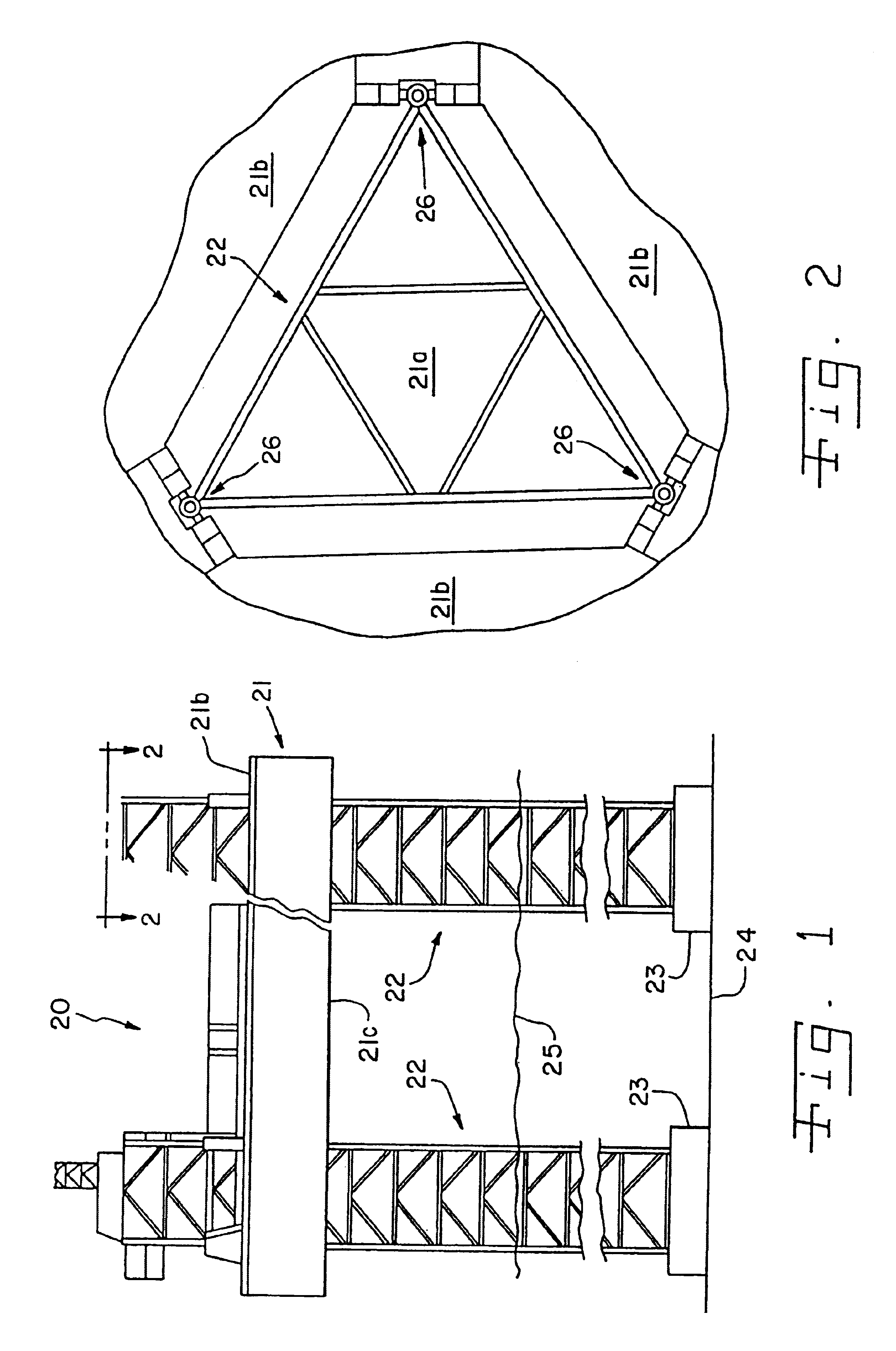
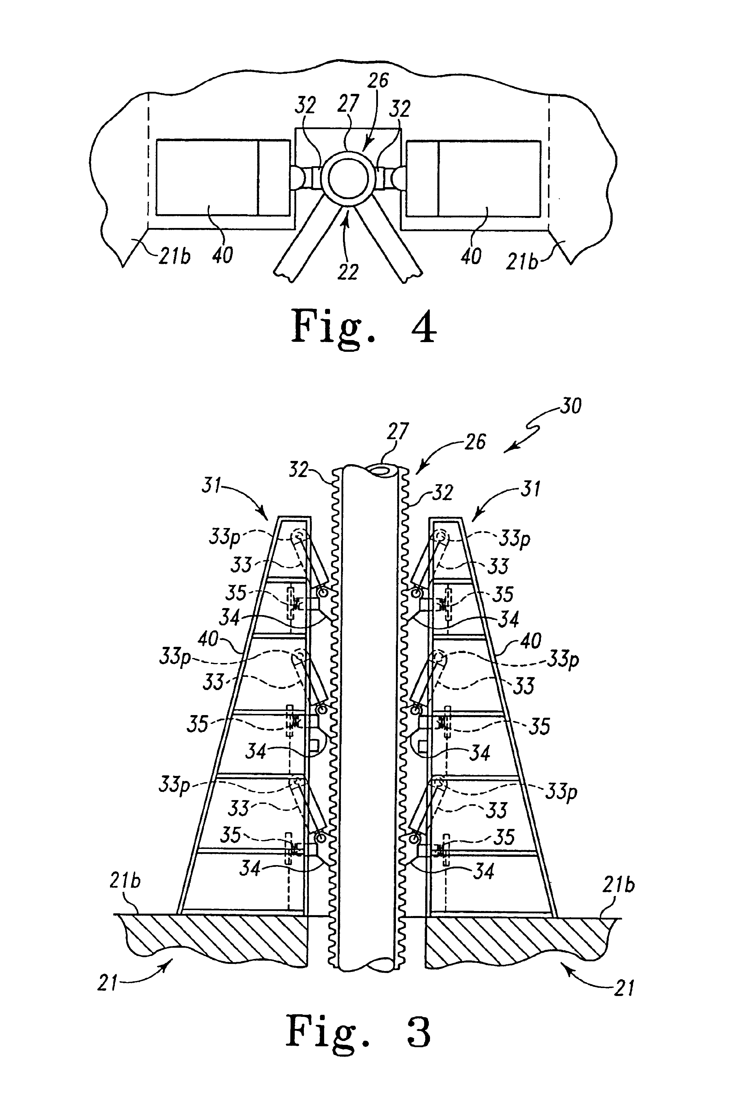
[0032]FIG. 1 illustrates a jack-up MODU 20 at an offshore drilling site. MODU 20 comprises a platform structure 21, and a plurality of MODU supporting legs 22. Jack-up MODU 20 also includes a jacking system, as described herein, to provide relative motion between the MODU platform 21 and the plurality of supporting legs 22. As illustrated in FIG. 1, MODU platform 21 is supported by the MODU legs 22 from the earth's surface (because of their length, the MODU supporting legs 22 are shown only in part in FIG. 1) substantially above the water level 25.

[0033]As constructed and transported, the MODU platform 21 is in a position closely adjacent leg footings 23. The MODU platform 21 is buoyant so the MODU 20 comprises a vessel which can be towed to an exploration site. At the exploration site, the supporting legs 22 are lowered by the jacking system with respect to the platform 21 until the footings 23 reach the earth's surface 24, and the platform 21 is thereafter lifted by the jacking sy...


PUM


Abstract

In a jacking system for a marine platform, a plurality of hydraulic continuous linear motion motors are engageable with a plurality of marine platform supporting logs to provide relative motion between the platform and its supporting legs, and to also maintain the platform and its supporting legs locked in a stationary relationship. In the jacking system, the number of hydraulic piston / cylinder units and the number and design of the teeth that are engaged in providing relative motion may be selected to substantially reduce material stresses on the system.

Description

[0001]This application is a divisional application which claims the benefit of U.S. patent application Ser. No. 09 / 835,794, filed Apr. 16, 2001, now U.S. Pat. No. 6,652,194.FIELD OF THE INVENTION[0002]This invention relates to mobile offshore dwelling units (MODUs), and more particularly to MODU jacking systems, apparatus and methods.BACKGROUND OF THE INVENTION[0003]Offshore structures are not unknown. In 1955 the U.S. Army Corps. of Engineers constructed radar stations along the New England coast, which were commonly referred to as “Texas Towers.” In constructing these radar stations, the radar platforms were lifted on supporting legs, using hydraulic cylinders. While the legs and the platform were pinned together, a plurality of hydraulic cylinders were manually attached between the supporting legs and the platform. The pins holding the platform stationary with respect to the legs were removed, and the hydraulic cylinders were then pressurized to extend their pistons and raise the...

Claims


Application Information

Patent Timeline
Patent Type & Authority Patents(United States)
IPC IPC(8): E02B17/08B66F1/00E02B17/04
CPCE02B17/0818E02B17/04
Inventor INGLE, JAMES E.
Owner INGLE JAMES E
Why Eureka
Try Eureka