Suction roll with sensors for detecting temperature and/or pressure

a sensor and suction roll technology, applied in the field of industrial rolls, can solve the problems of affecting the quality of paper produced with the paper machine, presenting technical challenges that a conventional roll does not, and damage to sensors, so as to facilitate the use of a sensing system

Inactive Publication Date: 2006-01-03
STOWE WOODWARD
View PDF26 Cites 61 Cited by
  • Summary
  • Abstract
  • Description
  • Claims
  • Application Information

AI Technical Summary

Benefits of technology

[0013]Each of these aspects of the invention (as well as others) can facilitate the employment of a sensing system within a suction roll cover, thereby overcoming some of the difficulties presented by prior sensing systems.

Problems solved by technology

The magnitude of pressure applied with a suction roll can, therefore, impact the quality of paper produced with the paper machine.
However, a suction roll of the type described above presents technical challenges that a conventional roll does not.
Thus, drilling holes in the cover in a conventional manner would almost certainly damage the sensors, and may well damage the optical fiber.
Also, during curing of the cover often the polymeric material shifts slightly on the core, and in turn may shift the positions of the fiber and sensors; thus, it is not always possible to determine precisely the position of the fiber and sensors beneath the cover, and the shifting core may move a sensor or cable to a position directly beneath a hole.
Further, ordinarily optical cable has a relative high minimum bending radius for suitable performance; thus, trying to weave an optical fiber between prospective holes in the roll may result in unacceptable optical transmission within the fiber.

Method used


Image

  • Suction roll with sensors for detecting temperature and/or pressure
  • Suction roll with sensors for detecting temperature and/or pressure
  • Suction roll with sensors for detecting temperature and/or pressure

Examples


example

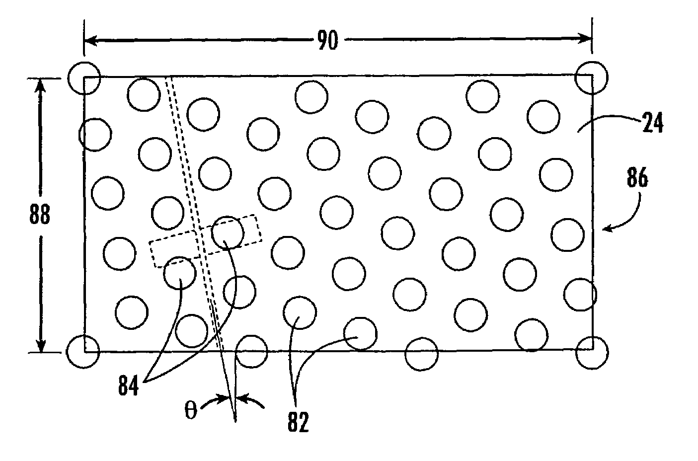
[0068]In this example, it is assumed that the roll has the dimensions set forth in Table 1, and that the hole pattern is that illustrated in FIG. 9.

[0069]

DimensionQuantityDiameter36inchesAxial Length of Roll between Outermost238inchesSensorsFrame0.725inchesDrill Spacing1.405inches

[0070]The diameter and frame measurements indicate that the variable N above is 156, and for the hole pattern of FIG. 9, the variable B is 9. Thus, for this roll, Equation 5 yields:

α=0.041z  Equation 6

This equation can then be used to calculate axial and circumferential coordinates for sensors.

[0071]If the circumferential spacing is maintained to be the same as a typical roll (usually 21 sensors over a 360 degree circumference, or about 17.14 degrees between sensors), a set of circumferential and axial positions can be calculated (Table 2).

[0072]

Total AngleSimple AngleAxial PositionSensor No.(degrees)(degrees)(inches)10.0000.0000.02377.14317.14325.553754.28634.28651.1041131.42951.42976.6551508.57268.572101....


PUM

PropertyMeasurementUnit
widthaaaaaaaaaa
angleaaaaaaaaaa
angleaaaaaaaaaa

Abstract

An industrial roll includes: a substantially cylindrical shell having an outer surface and an internal lumen; a polymeric cover circumferentially overlying the shell outer surface; and a sensing system. The sensing system includes: a plurality of sensors embedded in the cover, the sensors configured to sense an operating parameter of the roll; and a signal-carrying member serially connected with and extending between the plurality of sensors. The signal-carrying member follows a helical path over the outer surface of the shell, wherein the signal-carrying member extends between adjacent sensors and extends over more than one complete revolution of the shell outer surface (and, preferably, an intermediate segment of the signal-carrying member extends over more than a full revolution of the roll between adjacent sensors).

Description

FIELD OF THE INVENTION[0001]The present invention relates generally to industrial rolls, and more particularly to rolls for papermaking.BACKGROUND OF THE INVENTION[0002]Cylindrical rolls are utilized in a number of industrial applications, especially those relating to papermaking. Such rolls are typically employed in demanding environments in which they can be exposed to high dynamic loads and temperatures and aggressive or corrosive chemical agents. As an example, in a typical paper mill, rolls are used not only for transporting a fibrous web sheet between processing stations, but also, in the case of press section and calender rolls, for processing the web sheet itself into paper.[0003]A papermaking machine may include one or more suction rolls placed at various positions within the machine to draw moisture from a belt (such as a press felt) and / or the fiber web. Each suction roll is typically constructed from a metallic shell covered by a polymeric cover with a plurality of holes...

Claims


Application Information

Patent Timeline
Patent Type & Authority Patents(United States)
IPC IPC(8): B05C1/08B30B15/00G01L5/00D21F3/06D21F3/10F16C13/00G01K1/02G01K13/08G08C23/04
CPCD21F3/105D21F3/06
Inventor GUSTAFSON, ERIC J.
Owner STOWE WOODWARD
Why Eureka
Try Eureka