
Hardened steel components and process of treating the same

Inactive Publication Date: 2006-01-03
GKN DRIVELINE DEUTSCHLAND GMBH
View PDF20 Cites 8 Cited by
  • Summary
  • Abstract
  • Description
  • Claims
  • Application Information

AI Technical Summary

Benefits of technology

[0019]Tempering preferably takes place at a temperature of approximately 175° C. For the purpose of reducing hardness stresses, the components are heated in a furnace to said temperature which is then held for a period of approximately 1 hour. Higher tempering temperatures can lead to a reduced hardness of the diffusion zone and induction-hardened layer.
[0020]Acc

Problems solved by technology

Such loads which are present in the form of Hertzian pressure can lead to the formatio

Method used


Image

  • Hardened steel components and process of treating the same
  • Hardened steel components and process of treating the same
  • Hardened steel components and process of treating the same

Examples


Example

DETAILED DESCRIPTION OF THE DRAWINGS

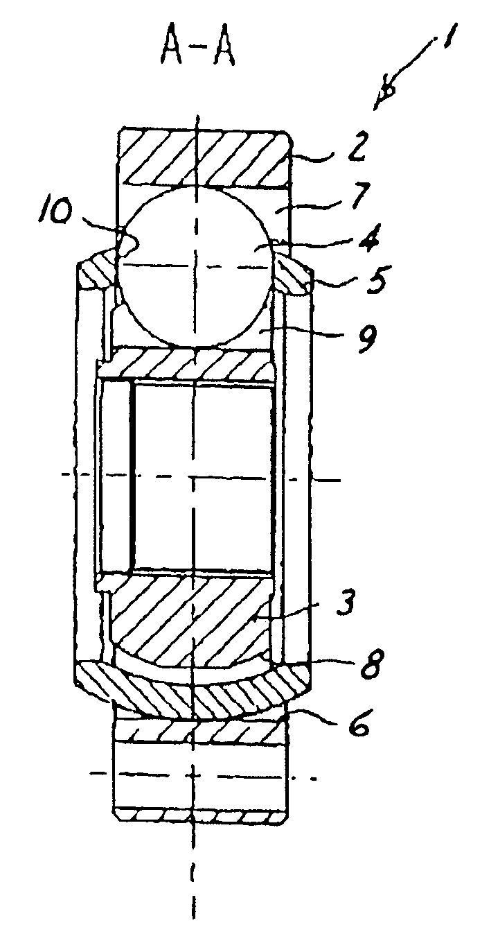
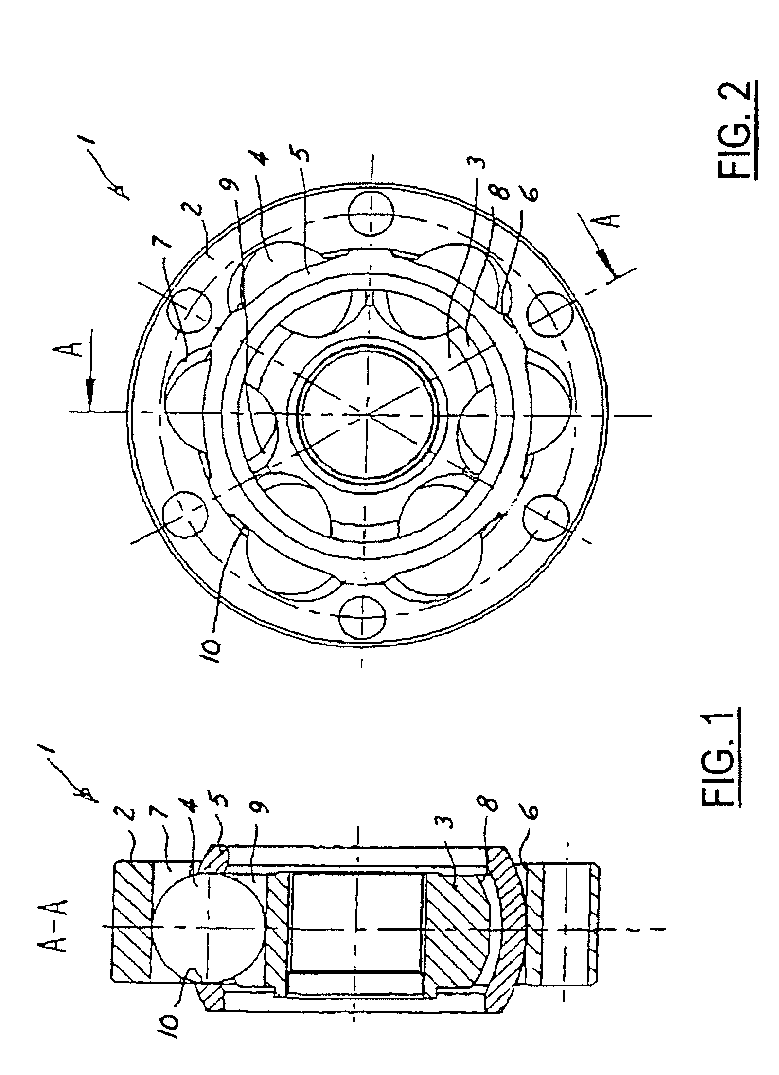
[0025]FIGS. 1 and 2 will be described jointly below. They show a constant velocity plunging joint 1 in the form of a VL joint with an annular outer joint part 2 and an annular inner joint part 3 as well as balls 4 for transmitting torque between the two joint parts, and furthermore a cage 5 for guiding the balls 4. The outer joint part 2 comprises a cylindrical guiding face 6 for guiding the cage 5, and outer running grooves 7. The inner joint part 3 comprises an outer face 8 and an inner running grooves 9. The inner and outer running grooves 7, 9 form circumferentially alternating angles of intersection with the longitudinal axes of the outer joint part 2 and of the inner joint part 3. In inner and outer running grooves 7, 9 associated with one another there is guided a ball 4 held in a window 10 of the cage 5.

[0026]The outer joint part 2 is provided with bores 11 for bolting on a flange. The inner joint part 3 is provided with a longitudinally t...


PUM

PropertyMeasurementUnit
Temperatureaaaaaaaaaa
Thicknessaaaaaaaaaa

Abstract

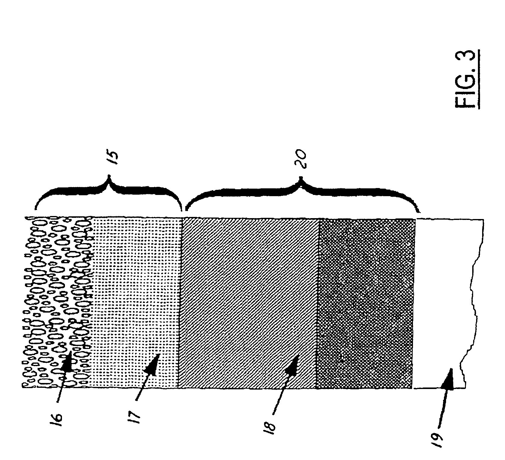
The invention relates to components made of steel, more particularly outer joint parts and inner joint parts of constant velocity joints, and to a process of heat treating such components made of steel. The heat treatment operation includes the process stages of nitriding, induction surface layer hardening and tempering, which processes follow one another. As a result of the nitriding operation, the joint parts are provided with a surface layer (15) including nitrides and a diffusion layer (18) positioned thereunderneath. The subsequent induction hardening process causes the diffusion layer (18) to be hardened, so that it comprises good supporting characteristics for supporting the surface layer (15) positioned above same.

Description

BACKGROUND[0001]The invention relates to components made of steel for establishing contact with rolling contact members, more particularly outer joint parts (2) and inner joint parts (3) of constant velocity joints, as well as sleeves and journals of ball-guided longitudinal plunging pieces, and to a process of heat-treating such components.[0002]In constant velocity joints with an outer joint part and an inner joint part and with torque transmitting rolling contact members which are held in running grooves in the outer part and inner part and roll therein, there occur high pressures between the rolling contact members and the running grooves in the inner part and outer part. Such loads which are present in the form of Hertzian pressure can lead to the formation of pitting which, in the final analysis, causes the constant velocity joints to fail. Similar conditions prevail in the case of ball-guided longitudinal plunging pieces provided for torque transmitting purposes wherein sleev...

Claims


Application Information

Patent Timeline
IPC IPC(8): C21D9/40C21D1/06F16D3/20C21D1/10C21D1/78C21D9/00C23C8/26C23C8/38C23C8/50C23C8/80F16D3/223
CPCC21D9/40F16D3/223C23C8/80C21D1/10C21D1/78C21D9/0068Y10T428/24975F16D2300/10Y10T428/26Y10T428/265Y02P10/25F16D2250/0053
Inventor SCHUSTER, MANFRED
Owner GKN DRIVELINE DEUTSCHLAND GMBH
Learn More