LED device including phosphor layers on the reflecting surface

a technology of led devices and reflecting surfaces, which is applied in the direction of discharge tubes/lamp details, discharge tubes luminescnet screens, electric discharge lamps, etc., can solve the problems of low luminance of white led devices, reduced practical use, and less reproducibility of especially reds, and achieve excellent color reproducibility and high luminance

Active Publication Date: 2006-01-03
LEDCOMM LLC
View PDF8 Cites 91 Cited by
  • Summary
  • Abstract
  • Description
  • Claims
  • Application Information

AI Technical Summary

Benefits of technology

[0006]Thus, it is an object of the present invention to provide an LED device as a light source having excellent color reproducibility and high luminance.

Problems solved by technology

However, the pseudo-white light is not obtained by a color mixture of three primary colors, i.e., red, green and blue, resulting in a disadvantage of less reproducibility of especially red.
As the phosphors emitting red, blue and green lights have a low excitation efficiency or a low wavelength-conversion efficiency, luminance of the white LED device is low, resulting in a disadvantage of being off from practical use.

Method used


Image

  • LED device including phosphor layers on the reflecting surface
  • LED device including phosphor layers on the reflecting surface
  • LED device including phosphor layers on the reflecting surface

Examples


Embodiment Construction

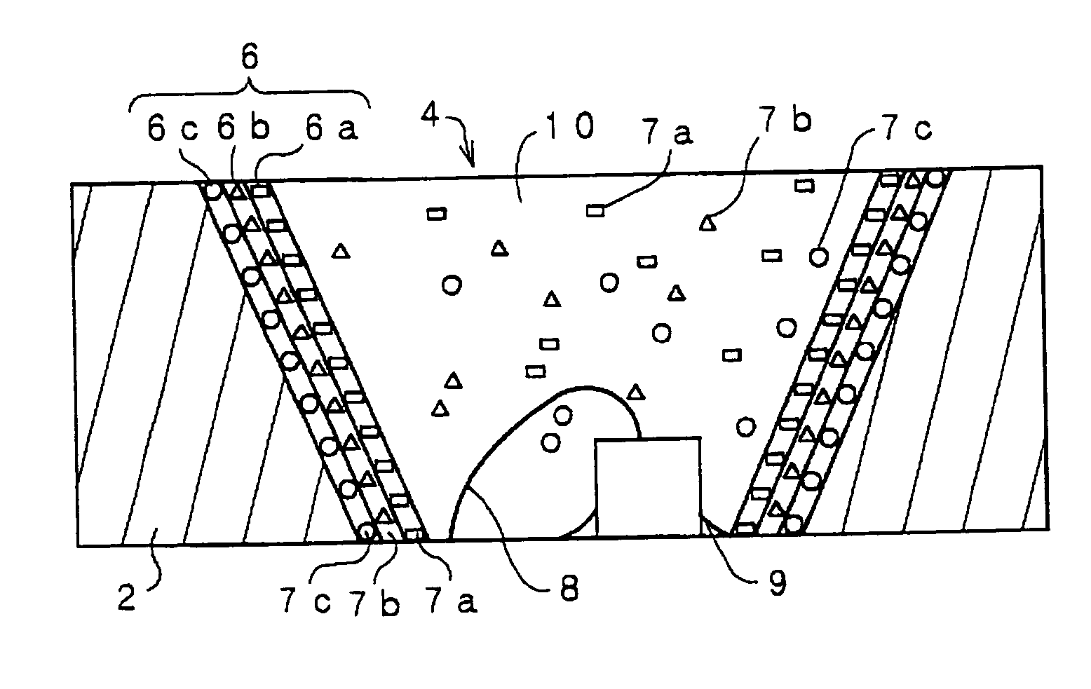
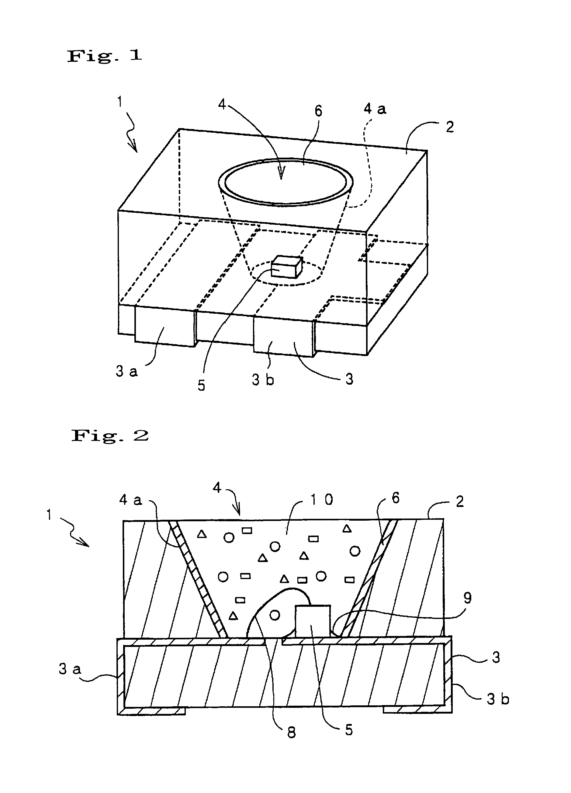
[0049]FIG. 1 is a perspective view of an LED device 1 according to the present invention and FIG. 2 is a sectional view thereof. The LED device 1 is provided with a rectangular base 2 and metal frames 3 for electrical connection. The base 2 comprises resin material, for example, AMODEL®, VECTRA® and so on having a high reflection efficiency of visible light. In the middle portion of the base 2, a mortar-like or cone-like recess 4 with the upper surface opened is formed. On the inner bottom of the recess 4 and on the metal frame 3, an LED chip (light emitting diode) 5 is disposed. The inner wall surface (reflection surface) 4a of the mortar-like recess 4 is arranged to reflect light emitted from the LED chip 5 to prevent the base 2 from absorbing the emitted light. The metal frames 3 are disposed in the base 2 when insert molding the base 2 and comprises terminal electrodes 3a, 3b.

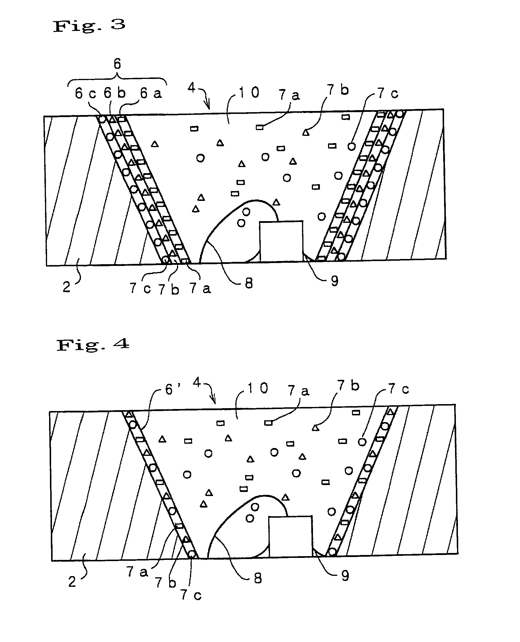
[0050]On the inner wall surface 4a of the recess 4, a phosphor layer 6 is formed. The phosphor layer 6 ...


PUM


Abstract

The present invention provides an LED device 1 as a light source having an excellent color reproducibility and high luminance. The LED device 1 comprises: a base 2 having a recess 4 with the upper surface opened, the inner wall surface of the recess 4 constituting a reflection surface 4a; a LED chip 5 disposed on the inner bottom of the recess 4; a resin 10 filled in the recess 4, the resin 10 including phosphors 7a, 7b, 7c which absorb a part of light emitted from the LED chip to convert the wavelength thereof and emit light; and a phosphor layer 6a, 6b, 6c formed on the reflection surface 4a, the phosphor layer 6a, 6b, 6c including the phosphors 7a, 7b, 7c.

Description

BACKGROUND OF THE INVENTION[0001]The present invention relates to an LED device used mainly for backlight of liquid crystal display of personal digital assistant and so on and for all kinds of indicators. Particularly, the LED device has phosphors that are excited by light emitted from an LED to emit light of different wavelength from the light emitted from the LED and is used for an LED light source emitting white or neutral light.[0002]Recently, demand for cellular phone and so on using color LCD has been expanded. As a backlight source of the color LCD, a white LED device has been used. A white LED device 100 as shown in FIG. 14 is provided with a base 101 made of white-light reflecting resin, i.e., AMODEL®, VECTRA® and so on and metal frames 102. On the inside bottom of a mortar-like or cone-like portion of the base 101 and on the metal frame 102, an LED chip (light emitting diode) 103 is mounted. The LED chip 103 is a blue LED emitting light having a wavelength of around 460 nm...

Claims


Application Information

Patent Timeline
Patent Type & Authority Patents(United States)
IPC IPC(8): H01L33/00H01J1/63H01L33/50H01L33/54H01L33/56H01L33/60H05B33/14
CPCH05B33/145H01L2224/48091H01L2224/73265H01L2224/45144H01L2924/00014H01L2924/00H01L33/486H01L33/502H01L33/504H01L33/60
Inventor OMOTO, MASATOSHI
Owner LEDCOMM LLC
Why Eureka
Try Eureka