Method and apparatus for visualization and manipulation of real 3-D objects in networked environments

Inactive Publication Date: 2006-01-03
OPEN VISUAL
View PDF6 Cites 25 Cited by
  • Summary
  • Abstract
  • Description
  • Claims
  • Application Information

AI Technical Summary

Benefits of technology

[0007]Accordingly, an object of the present invention is to provide a new visualiz

Problems solved by technology

The trouble with this existing paradigm is that the rendering process is computationally expensive.
These approaches naturally result in rendered images that are less-than-real, especially for natural complex objects that are difficult to model.
Although the modeling step may be performed off-line and thus is amenable to extremely complicated algorithms, the rendering step must be performed real-time for realistic m

Method used


Image

  • Method and apparatus for visualization and manipulation of real 3-D objects in networked environments
  • Method and apparatus for visualization and manipulation of real 3-D objects in networked environments
  • Method and apparatus for visualization and manipulation of real 3-D objects in networked environments

Examples


Embodiment Construction

A. IMAGE ACQUISITION DEVICE

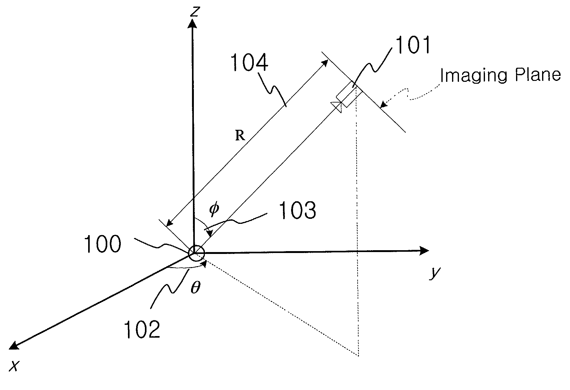
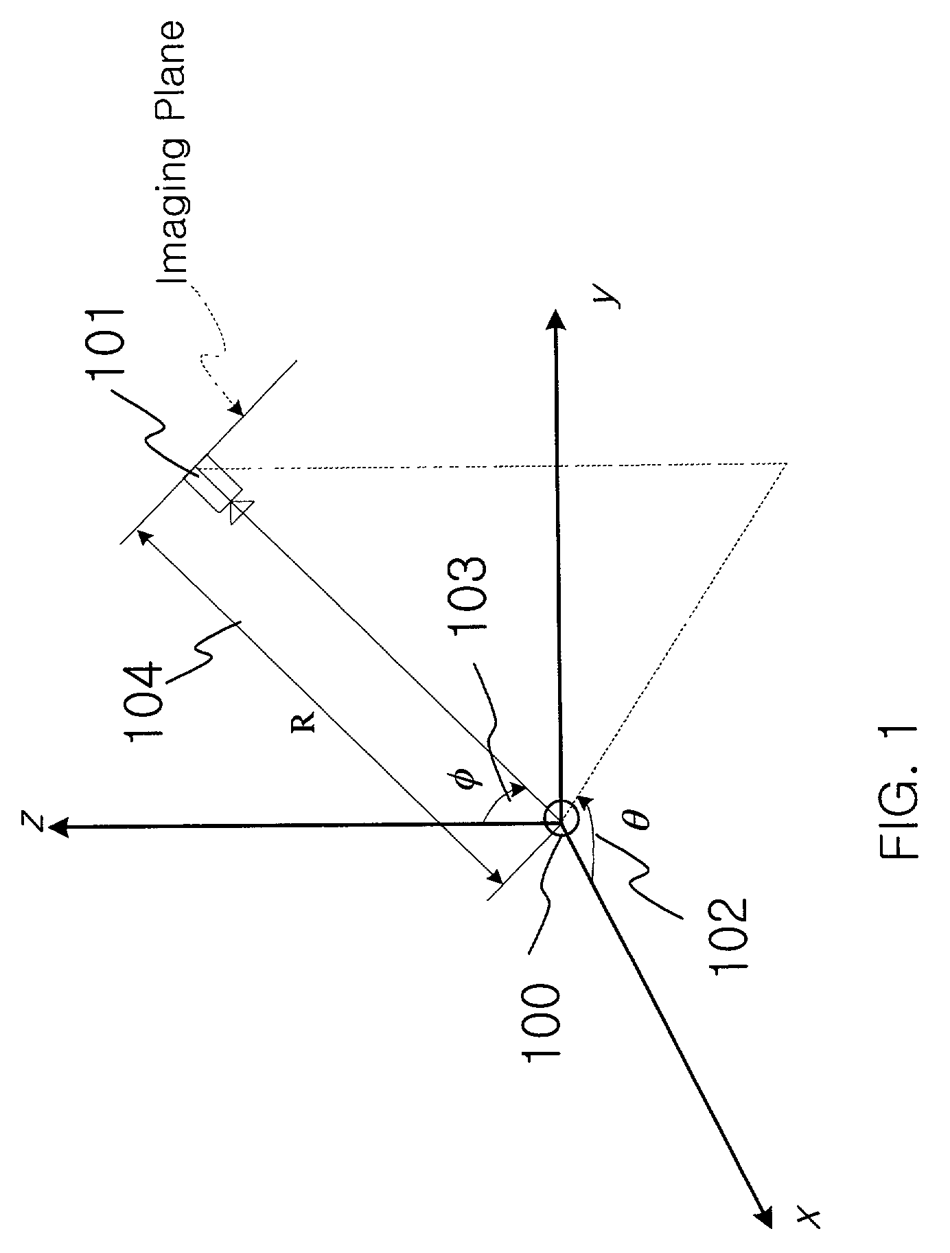
[0021]FIG. 1 shows the geometry of the image acquisition device. The object 100 is placed in the center (origin) and the camera 101 rotates about the object to capture images at various prescribed angle θ102 and φ103 at distance R 104, where θ102 is an azimuth in the horizontal plane and φ103 is an elevation from the horizontal plane. However, in order to reproduce the image of the object at a particular view angle that the user may request, the object must be imaged from “all possible view angles”. The definition of “all possible view angles” can be realized by drawing a subset of all possible rays (“all possible view angles”) from the origin.

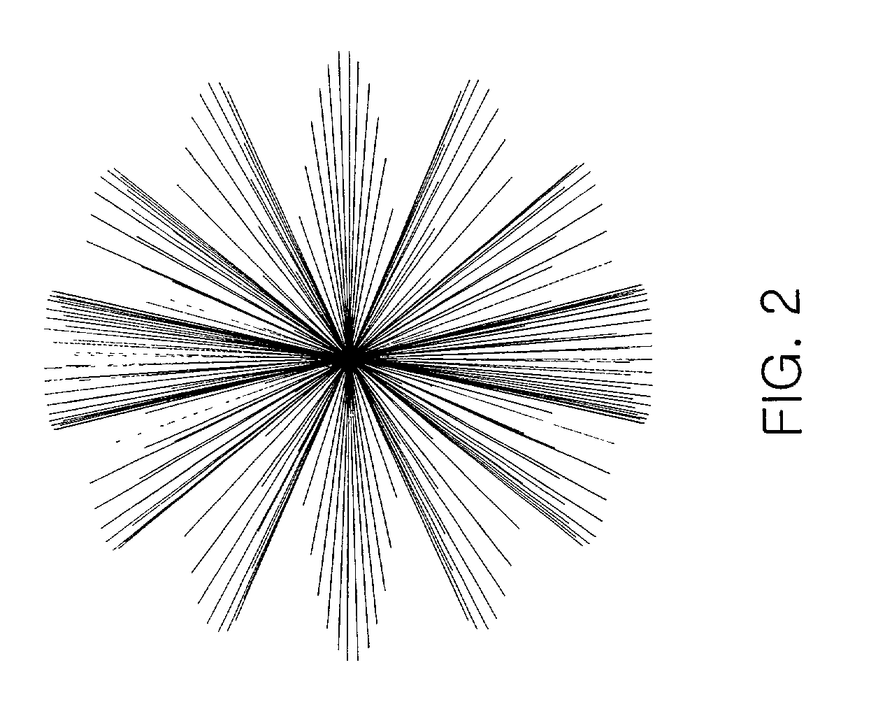
[0022]FIG. 2 shows a “fuzz-ball” formed by all such rays viewed together. In the figure, θ and φ are sampled as θ=2πm / 32 and φ=(0.5+n)π / 7, where m=0,1,K,31 and n=0,1,K,6. Notice that the ray spacing basically controls the viewing resolution, in the corresponding direction θ and φ. The viewing resolution determines th...


PUM


Abstract

A new method and apparatus for visualization and manipulation of real 3-D objects are disclosed. This new approach utilizes compressed digital video taking advantage of modern video compression technology. The entire system consists of the image acquisition device, the viewing/manipulation program and the 3-D image database. The system first captures images of the object from all possible view angles as a sequence of images (a video). As neighboring images within the sequence will generally be similar, the sequence will be amenable to standard video compression techniques such as MPEG. The acquired video data (rendition of a real 3-D object) is then stored into a database for later access, for instance, over the Internet.
Through specially developed software, the stored data can be manipulated while viewing the object. The user simply inputs—via a mouse, for instance—the view angle and the software automatically displays the appropriate frame within the video (stored data). The software allows various object manipulations such as rotation in arbitrary direction, as well as zoom, pan, etc. A particular implementation of the viewing program using a Pentium III processor, randomly accessing an MPEG sequence, through pre-decoding of certain anchor frames, is able to decode fast enough for users to perform real-time manipulation of the object.
The captured 3-D image data of an object is stored into a centralized (or distributed) database and users may access the data through the assigned URL for the object over the Internet. The data may or may not be password protected. As such, the overall system is an implementation of a one-stop service for individuals wishing to provide 3-D visualization of real 3-D objects over the Internet.

Description

RELATED APPLICATION[0001]This application claims the benefit of co-pending U.S. Provisional Application No. 60 / 285,044, filed on Apr. 19, 2001, entitled “Method and Apparatus for Visualization of Real 3-D Objects in Networked Environments.”BACKGROUND OF THE INVENTION[0002]I. Technical Field[0003]This invention relates generally to visualization. More particularly, this invention relates to visualization and manipulation of a real 3-D object using image acquisition and video compression.[0004]II. Description of the Related Art[0005]The essential goal of visualizing a real 3-D object is to render an image of the object depending on the user's view angle. Traditionally, this has been in the realm of computer graphics where images are rendered based on object models, be it mesh or otherwise. The trouble with this existing paradigm is that the rendering process is computationally expensive. Although there exist sub-optimal methods that can speed up the rendering process, these are basica...

Claims


Application Information

Patent Timeline
IPC IPC(8): G06K9/00G06T17/00G06K9/36G06T15/00G09G5/00H04N7/173
CPCG06T15/00H04N7/17336H04N21/21805H04N19/61H04N21/4143H04N21/6125H04N21/6587H04N21/234381G06T2200/16G06T17/00
Inventor SONG, SAMUEL MOON-HO
Owner OPEN VISUAL
Why Eureka
Try Eureka