Distributed active transmit and/or receive antenna

Active Publication Date: 2006-01-03
COMMSCOPE TECH LLC
View PDF138 Cites 241 Cited by
  • Summary
  • Abstract
  • Description
  • Claims
  • Application Information

AI Technical Summary

Problems solved by technology

Coaxial cables, however, introduce power losses that are proportional to length.
To overcome these power losses, substantial amplification is typically required, which necessitates the use of more expensive, higher power amplifiers.
In addition to increasing system material costs, the low loss cables characteristically have large diameter cross-sections.
Thus, along with the relatively long length of cable required by the system configuration, the large diameter of the cables can contribute towards making a system vulnerable to damage sustained from high wind conditions.
That is, the dimensions of the cables increase the wind friction experienced by the system.
System architects may consequently implement costly preventative design features and expect periodic cable disconnections and other repairs.
As discussed herein, insertion losses associated with the cables may necessitate some increases in the power amplification.
A ground level infrastructure or base station typically provides the compensatory amplification, thus further increasing the expense per unit or cost per watt.
In this case, half of the power has been consumed in cable loss / heat.
Operating characteristics of such divider equipment may introduce further insertion losses associated with the equipment, itself.
While helpful in mitigating some insertion losses associated with cables running up the towers to the antenna(s), such placement of the amplifiers still fails to address insertion losses associated with the jumper cable that connects the amplifier to the antenna, as well as any power divider disposed therebetween.
Thus, failure of a single amplifier, divider or other amplifying component may effectively render the entire system inoperable.
In this manner, the reliability of a system having multiple elements remains undermined by the collective dependence of the respective elements on common components.
Furthermore, the relative inaccessibility of the amplification equipment attributable to its proximity to the to the tower mast can compound repairs and other maintenance.
Consequently, inefficiencies associated with insertion losses continue to hinder operation and result in a relatively high cost of unit per watt.

Method used


Image

  • Distributed active transmit and/or receive antenna
  • Distributed active transmit and/or receive antenna
  • Distributed active transmit and/or receive antenna

Examples


Embodiment Construction

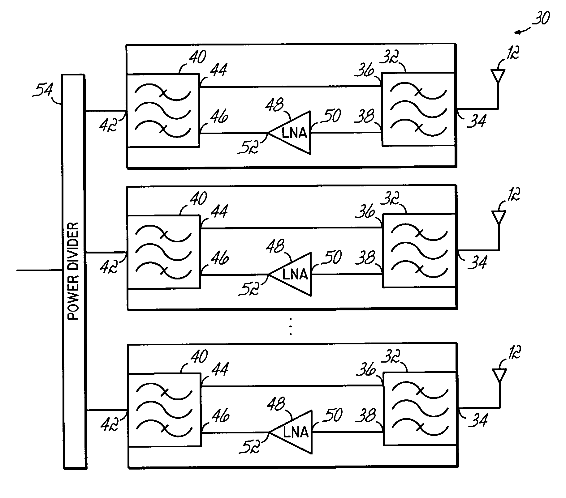
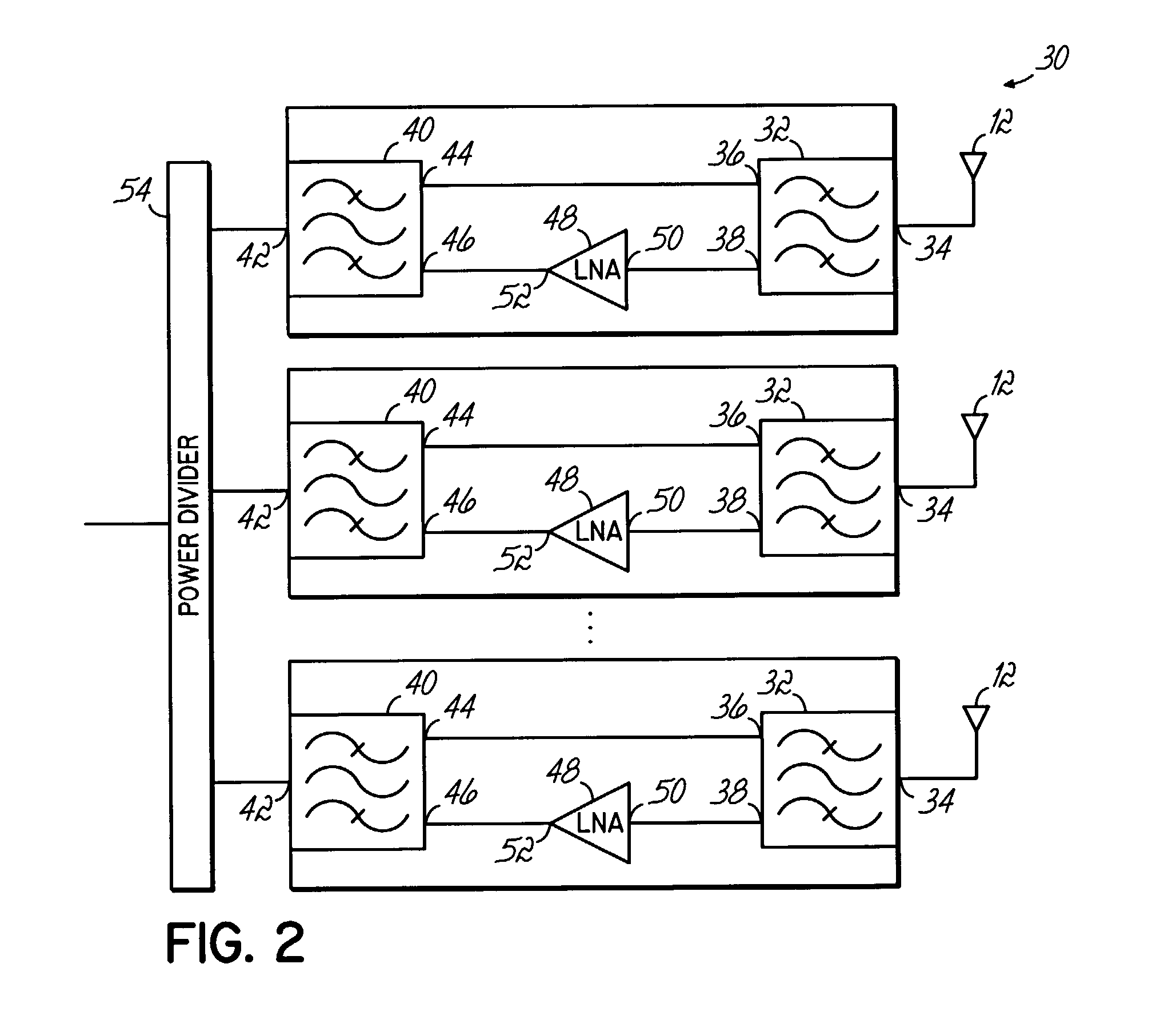
[0017]The invention addresses the above-discussed problems associated with the prior art by providing an antenna system 10 configured to improve cellular system performance by, in one respect, mitigating the occurrence of insertion losses through the use of an antenna incorporating an array of antenna elements and distributed amplifiers coupled to those individual elements in the array.

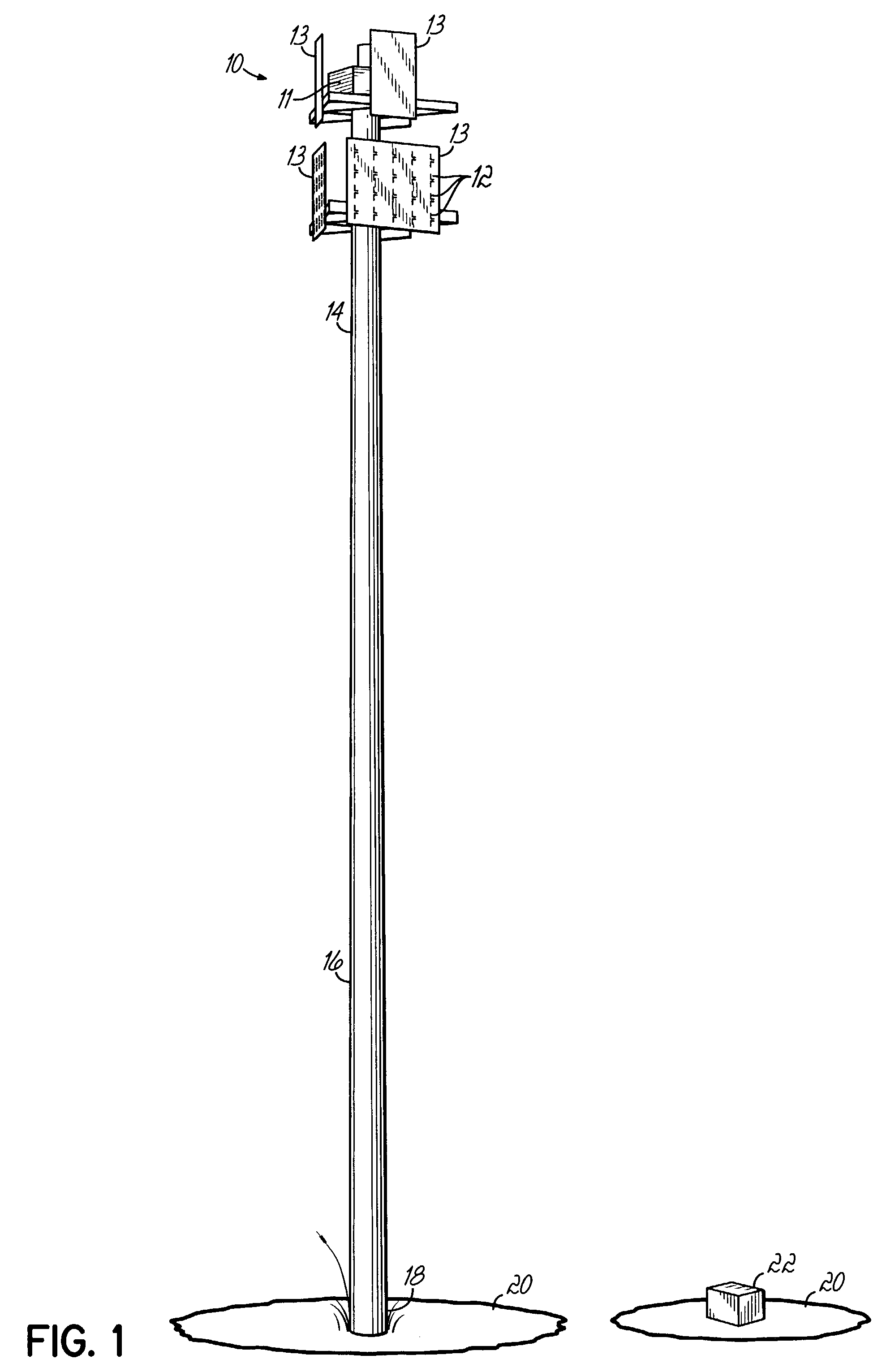
[0018]Referring generally to FIG. 1, there is shown an exemplary antenna system 10 in accordance with the precepts of the present invention. In order to achieve lower incidence of insertion loss, the antenna system 10 uses amplification equipment 11 disposed at the antenna element level. As such, exemplary antenna system 10 typically includes a plurality of beam width antenna arrays 13 suspended by a tower 16 or other support structure. Each antenna array 13 may include a plurality of antenna elements 12. The antenna arrays 13 may attach proximate the top 14 of the tower 16. Tower 16 may be supported ...


PUM


Abstract

A distributed antenna system comprising a plurality of antenna elements, duplexers and amplifiers, each amplifier and duplexer operatively coupled with one of said antenna elements and mounted closely adjacent to the associated antenna element in such a manner as incidences of insertion loss, noise and system failure are reduced.

Description

FIELD OF THE INVENTION[0001]This invention is directed generally to active antennas, and more particularly, to transmit and receive array antennas, such as those used in connection with cellular radio applications.BACKGROUND OF THE INVENTION[0002]Numerous communications applications, such as cellular and personal communications services (PCS), as well as multi-channel multi-point distribution systems (MMDS) and local multi-point distribution systems (LMDS), conventionally receive and retransmit signals from subscribers utilizing antennas mounted at the tops of towers or other structures. Other communications systems such as wireless local loop (WLL), specialized mobile radio (SMR), and wireless local area network (WLAN), have signal transmission infrastructure for receiving and transmitting communications between system subscribers that similarly utilize various forms of antennas and transceivers.[0003]All of these communications systems require amplification of the signals being tr...

Claims


Application Information

Patent Timeline
IPC IPC(8): H04B1/38H01Q1/12H01Q1/24H01Q21/00H01Q23/00H04Q7/20
CPCH01Q1/1242H01Q23/00H01Q21/0025H01Q1/246
Inventor HOPPENSTEIN, RUSSELLTHOMAS, MIKEJUDD, MANO D.
Owner COMMSCOPE TECH LLC
Why Eureka
Try Eureka