Power steering device

a technology of steering control device and power steering, which is applied in the direction of steering initiation, instruments, vessel construction, etc., can solve the problems of steering control device to perform a wrong operation, wrong steering control, and detection of torque detection means, so as to prevent steering control

Inactive Publication Date: 2006-01-10
TOYODA MASCH WORKS LTD
View PDF12 Cites 4 Cited by
  • Summary
  • Abstract
  • Description
  • Claims
  • Application Information

AI Technical Summary

Benefits of technology

[0017]Accordingly, it is a primary object of the present invention to provide an improved power steering device capable of preventing steering control from being wrongly performed even when the initial torque of a torque sensor cannot be detected normally due to a human error.
[0018]Another object of the present invention is to provide an improved power steering device which is capable of easily diminishing a residual torque to the level which no longer obstructs the steering control, without needing an experienced technical skill and a long adjustment work, so that there can be accomplished a reduced cost and stable performance.
[0022]With this construction, there are utilized those already provided for steering control such as assist power generating means like an electric motor or the like and torque detection means composed of the torsion bar and the pair of angle detection sensors arranged apart in the axial direction of the torsion bar. Thus, without introducing a large scale facility for such judgment, it becomes possible to judge whether the initial torque is normal or not, prior to shifting to the regular steering control state. That is, the detection of the initial torque by the torque detection means is performed as the assist power generating means cancels the positive and negative-going residual torques each other. Therefore, the residual torque included in the detected value of the initial torque is made small, and the steering control can be prevented from performing a wrong operation when it is shifted to the regular state, so that the stability in control can be improved. Consequently, with the positive and negative-going residual torques being canceled (eliminated), the origin torque which necessarily exists in the torque detection means composed of the torsion bar and the pair of angle sensors can be detected as precisely and quickly as possible as the initial torque which is to be detected in the initial setting of the power steering device.

Problems solved by technology

In the case of a pair of angle detection sensors like, e.g., twin resolvers as disclosed in Japanese unexamined, published patent application No. 2001-194251, it is quite difficult in ordinary manufacturing sites to assemble both sensors with the mounting angle positions thereof being in completely coincidence with each other, and thus, it is unavoidable that the torque detection means detects and indicates a torque which includes the torque (origin torque) depending on the difference between origin positions of the both sensors.
With respect to the residual torque, on the contrary, where the same remains involved in the detection value of the initial toque at the time of the initial setting, the residual torque is liable to cause wrong steering control when the imperfect returning of the steering handle is corrected upon shifting to the normal steering control state.
However, where the aforementioned operation (ii) is performed by an unskillful worker, it is often the case that the elimination (reduction) of the residual torque becomes insufficient (imperfect) thereby to permit the residual torque to remain (included) in a detection value of the initial torque.
This causes the steering control device to perform a wrong operation upon shifting to the regular steering control operation.
Further, even where the aforementioned operation (ii) is carried out reliably,. the detection of the initial torque cannot be done normally for the following reasons if the worker fails to perform the operation for holding the steering handle stationarily at the neutral position in the aforementioned operation (iii).
This also causes the steering control device to perform a wrong operation upon shifting to the regular steering control operation.
This disadvantageously gives rise to problems such as an increase in the manufacturing cost, the adjustment error in car dealers due to the short of skillful mechanics and the like in installing power steering devices as standard accessories on vehicles.

Method used


Image

  • Power steering device
  • Power steering device
  • Power steering device

Examples


first embodiment

(First Embodiment)

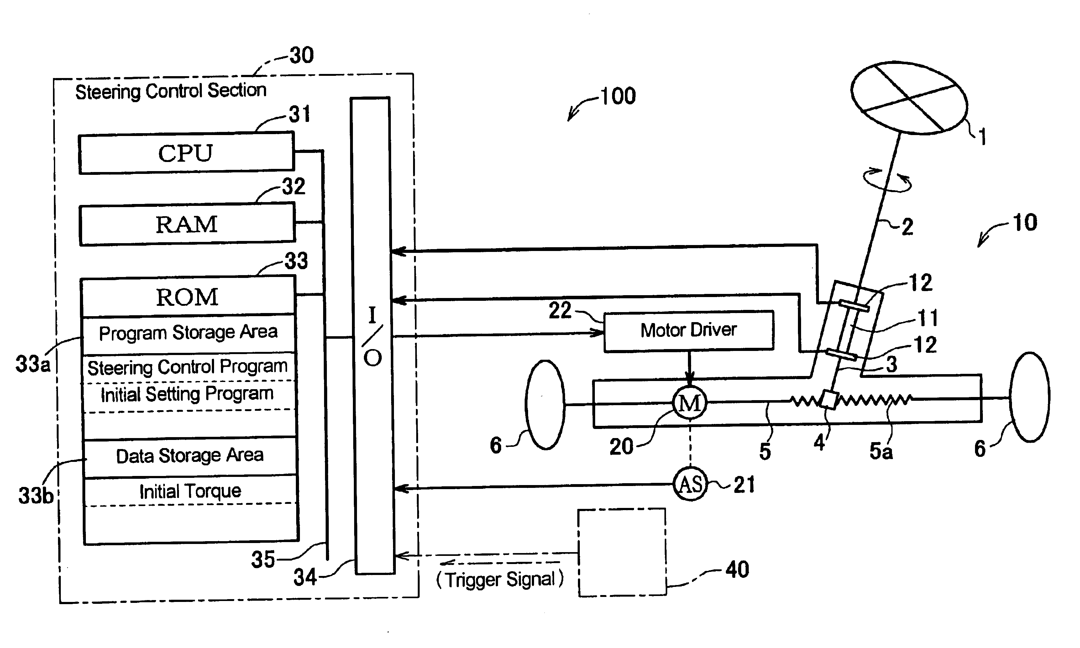
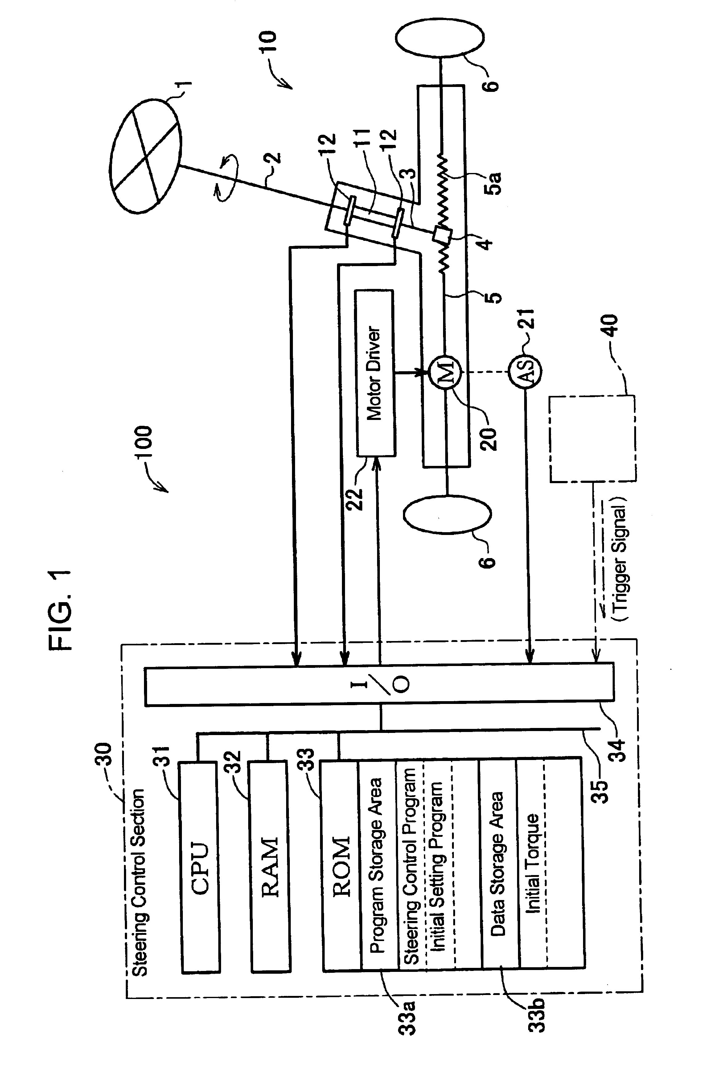
[0030]Hereafter, a power steering device in the first embodiment according to the present invention will be described with reference to the accompanying drawings. FIG. 1 schematically shows the general construction of an electric power steering device as one example of the power steering devices to which the present invention is applied. Although the term “vehicle” herein means an automobile or motorcar, the present inventions is not limited only to the automobile or motorcar. The electric power steering device 100 (hereinafter referred to as “power steering device”) has a steering handle 1 connected to a handle shaft 2, and a pinion shaft 3 connected to the handle shaft 2 through a torsion bar 11 is provided with a pinion 4, which is in meshing engagement with rack teeth 5a of a steering shaft 5. The steering shaft 5, when moved reciprocatively in its axial direction, causes the steered angle of the steerable wheels 6, 6 to be altered. Further, on the steering sha...

second embodiment

(Second Embodiment)

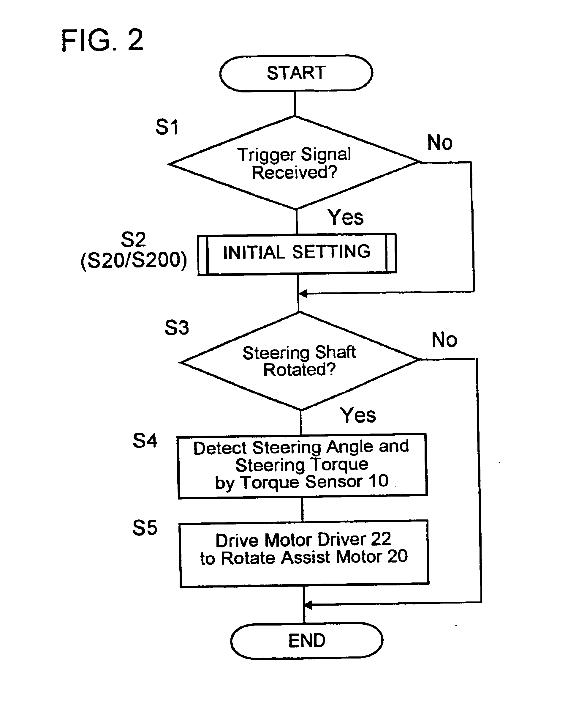
[0063]Next, a power steering device 100 in the second embodiment will be described in detail with reference to FIGS. 1, 2 and 6. The power steering device 100 in the second embodiment takes the same construction as that shown in FIG. 1 and is controlled in accordance with the steering control program shown in FIG. 2 whose initial setting program S2 is altered as shown in FIG. 6. Therefore, the descriptions as to the construction shown in FIG. 1 and as to the operation thereof in accordance with the steering control program shown in FIG. 2 apply in this second embodiment.

[0064]In the second embodiment, when having the trigger signal input thereto, the CPU 31 reads the initial setting program from the program storage area 33a of the ROM 33 and executes at least the following processing of the read-out program in the order of steps described below. That is, the CPU 31:[0065](i) operates the assist motor 20 to rotate the steering handle 1 which is being stationarily h...


PUM


Abstract

A power steering device is provided which is capable of preventing a wrong operation from occurring in a steering control state even when an initial torque of torque detection was not detected normally due to a human error. Upon receipt of a trigger signal, a CPU reads an initial setting program from a program storage area of a ROM and executes the initial setting program in the following order of steps. That is, the CPU detects by torque detection an initial torque which is generated primarily by the cause of the difference between origin positions of a pair of resolvers 12, 12 which together with a torsion bar constitutes the torque detection. Then, the CPU operates an assist motor to rotate a steering handle from a neutral position a predetermined rotational angle in one direction about the handle axis to stop the steering handle at a first judgment position and detects a first judgment torque value by the torque detection with the steering handle being stopped at the first judgment position. Then, the CPU rotates the steering handle from the neutral position the same angular position in the other direction to stop the steering handle at a second judgment position and detects a second judgment torque value by the torque detection with the steering handle being stopped at the second judgment position. Further, the CPU judges whether the initial torque has been detected normally or not, based on the first and second judgment torque values.

Description

INCORPORATION BY REFERENCE[0001]This application is based on and claims priority under 35 U.S.C. sctn. 119 with respect to Japanese Applications No. 2003-73277 and No. 2003-73194 both filed on Mar. 18, 2003, the entire contents of which are incorporated herein by reference.BACKGROUND OF THE INVENTION[0002]1. Field of the Invention[0003]The present invention relates to a power steering device for vehicles such as automobiles or motorcars.[0004]2. Discussion of the Related Art[0005]Heretofore, as steering devices of vehicles and particularly, as those of automobiles or motorcars, there have been widespread power assist mechanisms (power steering devices) for steering manipulation. For this reason, these days such power steering devices are installed on almost all of the motorcars manufactured in factories. Therefore, it is often the case that the repair or replacement of such power steering devices is done at car dealers regardless of whether new cars or used cars. Generally, such pow...

Claims


Application Information

Patent Timeline
Patent Type & Authority Patents(United States)
IPC IPC(8): B62D5/04B62D6/10
CPCB62D6/10B62D5/049
Inventor KATOU, HIDEKIASADA, ATSUHISA
Owner TOYODA MASCH WORKS LTD
Why Eureka
Try Eureka