Piezoelectric actuator with compensator

a technology of actuator and compensator, which is applied in the direction of machines/engines, mechanical equipment, spraying equipment, etc., can solve the problem of high alloy cos

Inactive Publication Date: 2006-01-10
SDST SIEMENS DIESEL SYST TECH +1
View PDF11 Cites 5 Cited by
  • Summary
  • Abstract
  • Description
  • Claims
  • Application Information

AI Technical Summary

Benefits of technology

[0005]It is, therefore, the object of the invention to provide an alternative construction for a control valve which can enable the effects of thermal expansion to be reduced allowing a compact design of the device while maintaining low production costs.
[0009]One advantage of such a compensator for a piezoelectric actuator is that it can be designed as a very compact unit because the compensation member is substantially prevented from expanding in a radial direction by a respective housing. This suppression of radial expansion causes an even stronger expansion in an axial direction.

Problems solved by technology

A possible disadvantage to the use of this material is the high cost of the alloy.

Method used


Image

  • Piezoelectric actuator with compensator
  • Piezoelectric actuator with compensator
  • Piezoelectric actuator with compensator

Examples


Embodiment Construction

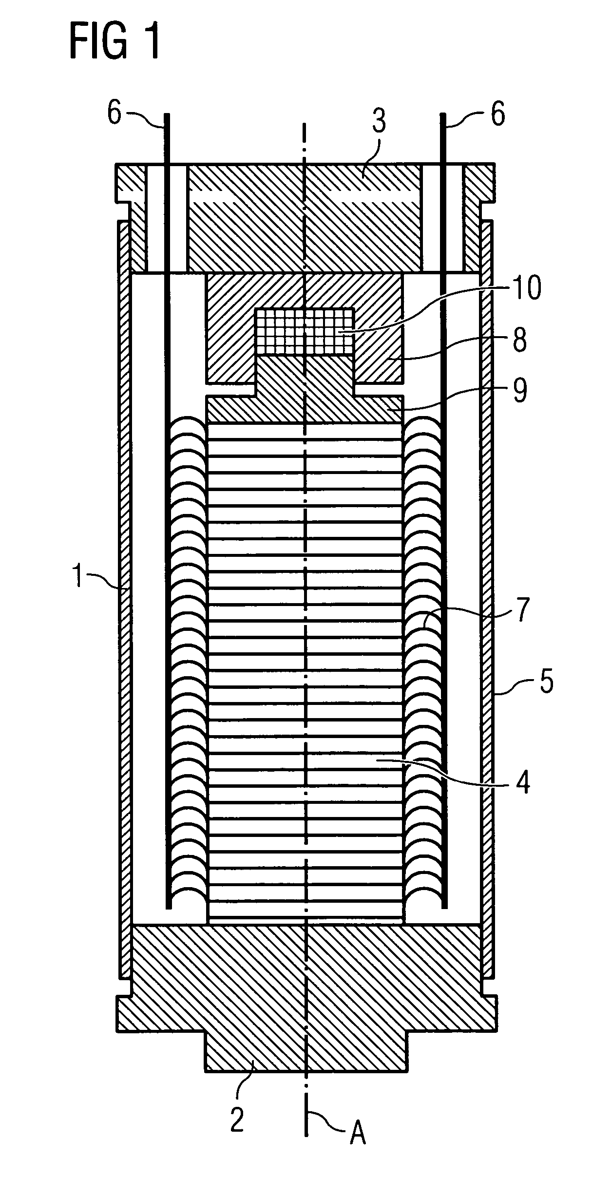
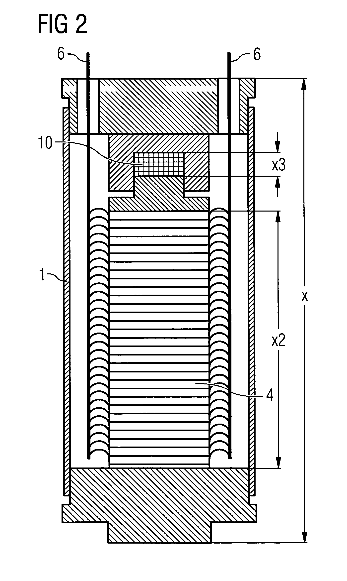
[0016]FIG. 1 shows a sectional view of piezoelectric actuator for use in, for example, a fuel injection valve. Axis A indicates the expansion axis along which the piezoelectric actuator expands to engage with, for example, a control valve member for opening or closing a valve (not shown). The actuator comprises a bottom end plate 2 and top end plate 3 between which a piezoelectric stack 4 is arranged. Top and bottom end plates 3 and 2 can be made from metal such as normal steel or any other suitable material. The piezoelectric stack consists of a plurality of piezoelectric elements and thus comprises a plurality of connecting wires 7 which are combined to two single wires 6 which are led through respective openings in the top end plate 3. The piezoelectric stack may have an exemplary expansion coefficient of 2×10⁻⁶ / K. On top of the piezoelectric stack between the top end plate 3 and the bottom plate 2 is a compensator device arranged in a suitable way to compensate thermal induced l...


PUM


Abstract

A temperature compensated actuator device comprises a piezoelectric stack having first and second ends along a central axis and having a first thermal expansion coefficient; and a compensator arranged on one end of the piezoelectric stack. The compensator comprises a first member in form of a cylinder; a second member in form of a piston plate wherein the first member and the second member are arranged movably along the axis with respect to each other and define a hollow space between them; and a compensation member having a thermal expansion coefficient higher than the first thermal expansion coefficient for filling the hollow space.

Description

BACKGROUND OF THE INVENTION[0001]The invention relates to a piezoelectric actuators and their application within fuel injector valves. Such a piezoelectric actuator may be to actuate a control valve such as a servovalve within fuel injection valve for controlling flow of a medium. These kind of valves can be used for the direct control of an injection needle within an fuel injection valve or indirect control of a needle by means of a control valve. These kind of valves usually comprise a housing having an inlet duct and an outlet duct and, a movable body which can reciprocate in order to control communication between the inlet and the outlet ducts, and drive means for the reciprocating movement of the body.[0002]A known valve of this kind includes a piezoelectric actuating member supported in a valve housing, the housing having an inlet duct and an outlet duct and a movable body which can be displaced by the actuating member in order to control in operation a flow of pressurized flu...

Claims


Application Information

Patent Timeline
Patent Type & Authority Patents(United States)
IPC IPC(8): B05B1/08B05B3/04F02M61/16F02M63/00H01L41/053
CPCF02M61/167H01L41/053F02M63/0026H10N30/886H10N30/88
Inventor AUGUSTIN, ULRICHKLUGL, WENDELIN
Owner SDST SIEMENS DIESEL SYST TECH
Why Eureka
Try Eureka