Laser projector having silhouette blanking for objects in the output light path

a technology of laser projector and object, applied in the field of laser projector, can solve the problems of less desirable candidates for laser-based projection apparatus, inherent cost, performance and/or color quality, and hinder the development effort to provide commercial quality laser projection

Inactive Publication Date: 2006-01-10
IMAX THEATERS INT
View PDF28 Cites 205 Cited by
  • Summary
  • Abstract
  • Description
  • Claims
  • Application Information

AI Technical Summary

Benefits of technology

[0020]It is an advantage of the present invention that it provides a method for updating information on obstruction of the display surface, allowing scanned lines to be re-enabled when tested for the continuing presence of an obstructing person or object.
[0021]It is a further advantage of the present invention that, by disabling only an obstructed portion of the display screen, it allows other, unobstructed parts of the display screen to be used.
[0022]It is yet a further advantage of the present invention that it provides a method for sensing and disabling laser projection in the event of failure in scanning system components.

Problems solved by technology

Other types of modulators, such as LCD and Digital Micromirror Device (DMD) area spatial light modulators, could be used for forming color images by modulating a laser light source; however, inherent cost, performance, and / or color quality drawbacks with these devices make them less desirable candidates for laser-based projection apparatus.
Although laser light offers advantages such as good color gamut and long component lifetimes, potential hazards associated with scanned coherent laser light are a concern that hinders development efforts to provide commercial quality laser projection.
However, a lingering area of concern for employing laser projectors relates to inadvertent, accidental exposure to laser illumination caused when an observer, located within the projected laser beam's path, looks back into the projector.
With laser-based projectors, however, a viewer can be at higher risk of eye damage, unless some form of protection is provided.
However, conventional interlock solutions would not be well suited for disabling laser-based projection when an audience member or some type of object is interposed in the path of projected light.
However, the aforementioned method of blanking the entire display screen is particularly annoying for many in the audience.

Method used


Image

  • Laser projector having silhouette blanking for objects in the output light path
  • Laser projector having silhouette blanking for objects in the output light path
  • Laser projector having silhouette blanking for objects in the output light path

Examples


Embodiment Construction

[0039]The present description is directed in particular to elements forming part of, or cooperating more directly with, apparatus in accordance with the invention. It is to be understood that elements not specifically shown or described may take various forms well known to those skilled in the art.

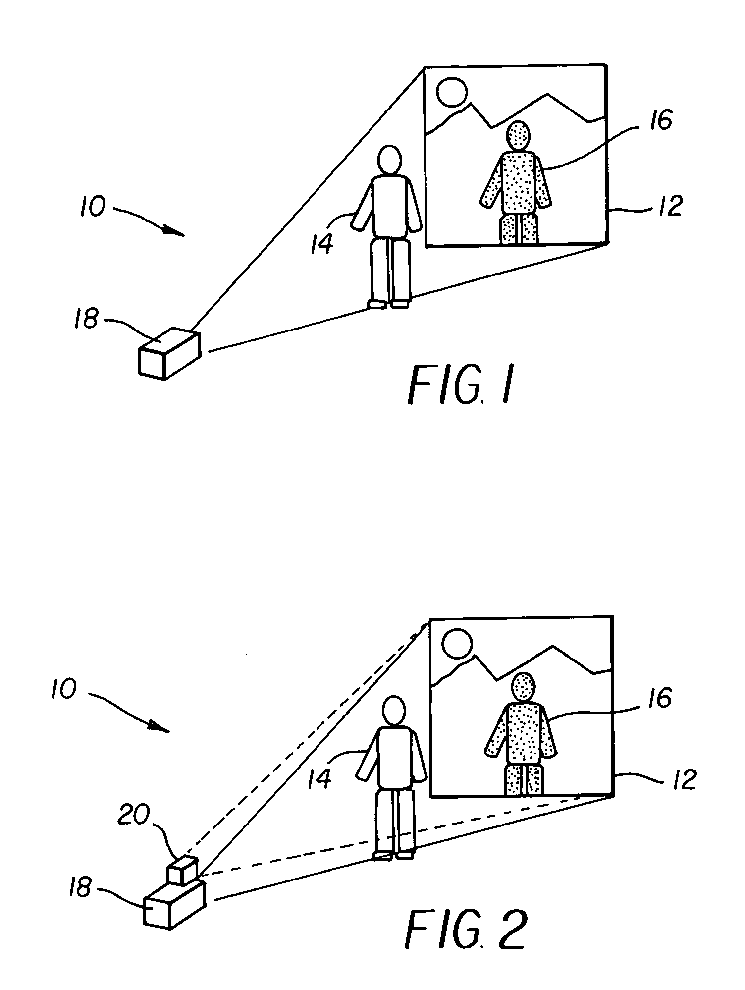
[0040]Laser-based projection devices form a two dimensional image by modulating and scanning a laser beam across a display surface, effectively tracing out successive rows or columns of spaced-apart pixel positions, where pixel-to-pixel spacing is typically equal throughout an image. One example of a laser-based projection device is disclosed in U.S. Pat. No. 6,476,848 (Kowarz et al.), the disclosure of which is incorporated herein by reference.

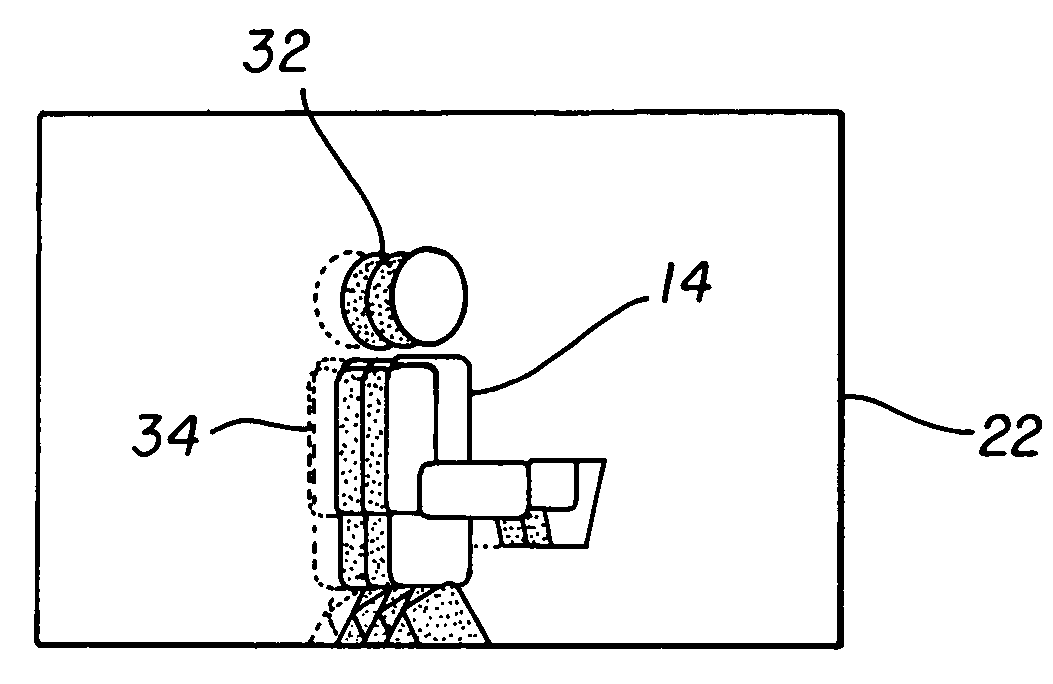
[0041]Referring to FIG. 1, there is shown a simplified perspective diagram of a front-projection system 10 comprising a laser-based projection apparatus 18, such as the projector of the Kowarz et al. disclosure, projecting onto a display surface 12....


PUM


Abstract

A projection apparatus (18) forms an image frame (22) on a display surface (12), where the image frame (22) is a two-dimensional array of pixels. The projection apparatus (18) has a laser (40) light source, an image modulator (42) for forming an image-bearing beam according to scanned line data, and projection optics (44) for projecting the image-bearing beam toward the display surface (12). A camera (20) obtains a sensed pixel array by sensing the two-dimensional array of pixels from the display surface (12). A control logic processor (28) compares the sensed pixel array with corresponding image data to identify any portion of the image-bearing beam that is obstructed from the display surface (12) and to disable obstructed portions of the image-bearing beam for at least one subsequent image frame (22).

Description

RELATED APPLICATIONS[0001]This application is related to the following copending U.S. patent application of the same assignee:[0002]“High-Contrast Display System with Scanned Conformal Grating Device” U.S. Ser. No. 10 / 171,252, filed Jun. 12, 2002 in the names of Marek W. Kowarz and James G. Phalen.FIELD OF THE INVENTION[0003]This invention generally relates to projection apparatus employing scanned laser light sources and more particularly relates to a laser projector that responds to an object detected in the output path by disabling the laser over at least a portion of the scan corresponding to the object.BACKGROUND OF THE INVENTION[0004]Numerous types of electronic projection apparatus have been proposed for projecting digital images. Currently, projection apparatus of this type serve primarily for business presentations and other types of projection apparatus. However, in the future, electronic projection apparatus are expected to compete with conventional film-based projectors,...

Claims


Application Information

Patent Timeline
Patent Type & Authority Patents(United States)
IPC IPC(8): G03B21/00G03B21/26H04N5/74H04N9/31
CPCH04N5/7416H04N9/3197H04N9/3194H04N9/3161
Inventor AGOSTINELLI, JOHN A.
Owner IMAX THEATERS INT
Why Eureka
Try Eureka