
Triple circuit turbine blade

a turbine blade and triple circuit technology, applied in the field of gas turbine engines, can solve the problems of limiting the useful life of the various turbine components exposed to the combustion gases during operation, reducing the cooling efficiency of the turbine blade, so as to achieve the effect of maximizing cooling efficiency and reducing bulk

Inactive Publication Date: 2006-01-10
GENERAL ELECTRIC CO
View PDF14 Cites 43 Cited by
  • Summary
  • Abstract
  • Description
  • Claims
  • Application Information

AI Technical Summary

Benefits of technology

"The patent describes a turbine blade design with internal cooling circuits that help improve its performance. The blade has a dovetail joint at the root, and three cooling circuits that run inside the blade. These circuits have inlet channels that align with each other and are positioned in the dovetail, platform, and airfoil. The channels twist together and help to cool the blade from the dovetail to the leading edge. This design helps to improve the efficiency and durability of turbine blades."

Problems solved by technology

Engine efficiency may be maximized by maximizing the temperature of the combustion gases, but the high combustion gas temperature will limit the useful life of the various turbine components exposed to the combustion gases during operation.
Excess backflow margin is not desirable since it leads to blow-off or lift-off of the spent cooling air as it is discharged from the outlet holes in typical film cooling configurations.
The turbulators and specific configurations of the cooling circuits introduce pressure losses or pressure drops in the cooling air prior to discharge from the various outlets.

Method used


Image

  • Triple circuit turbine blade
  • Triple circuit turbine blade
  • Triple circuit turbine blade

Examples


Embodiment Construction

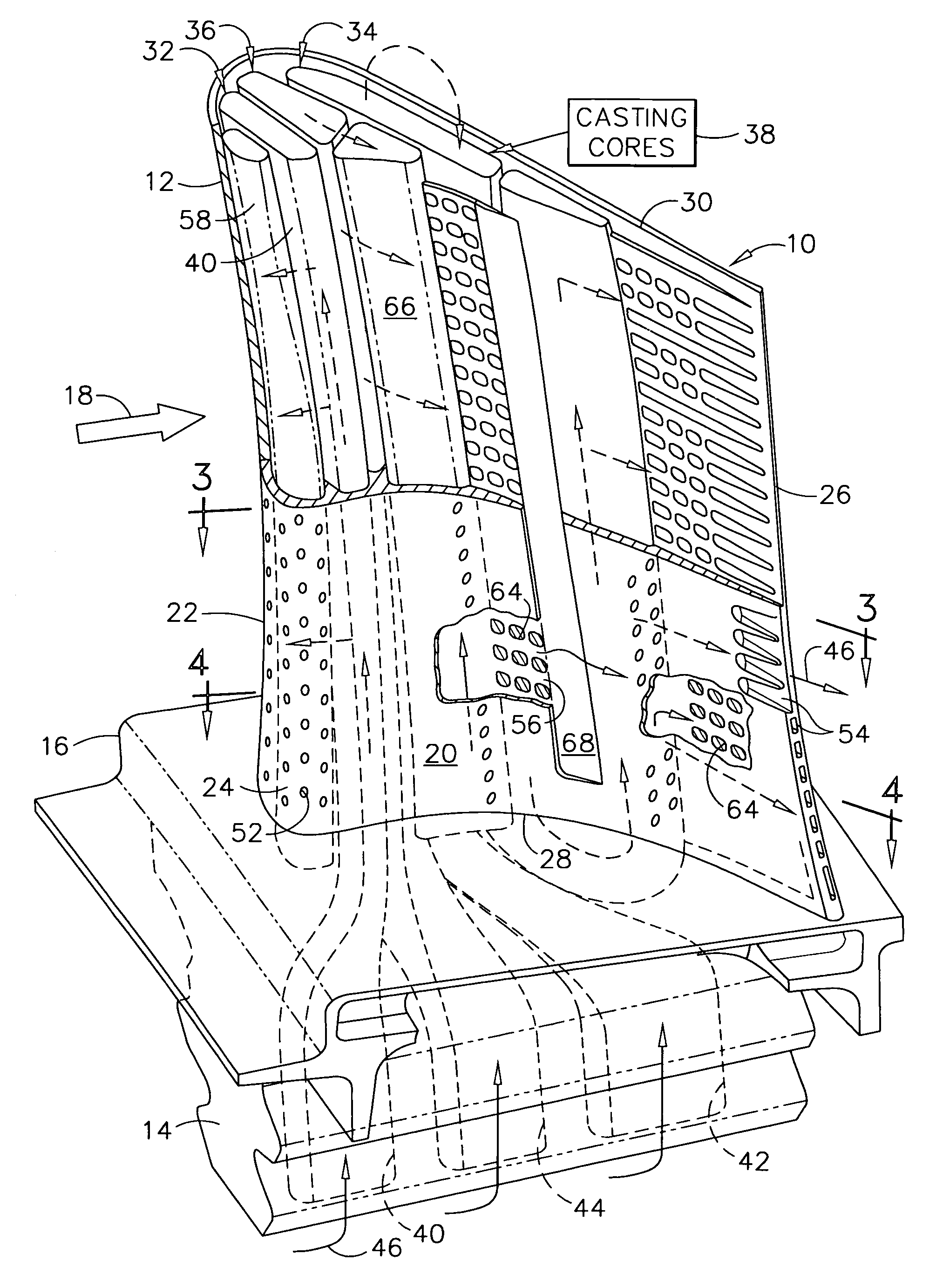
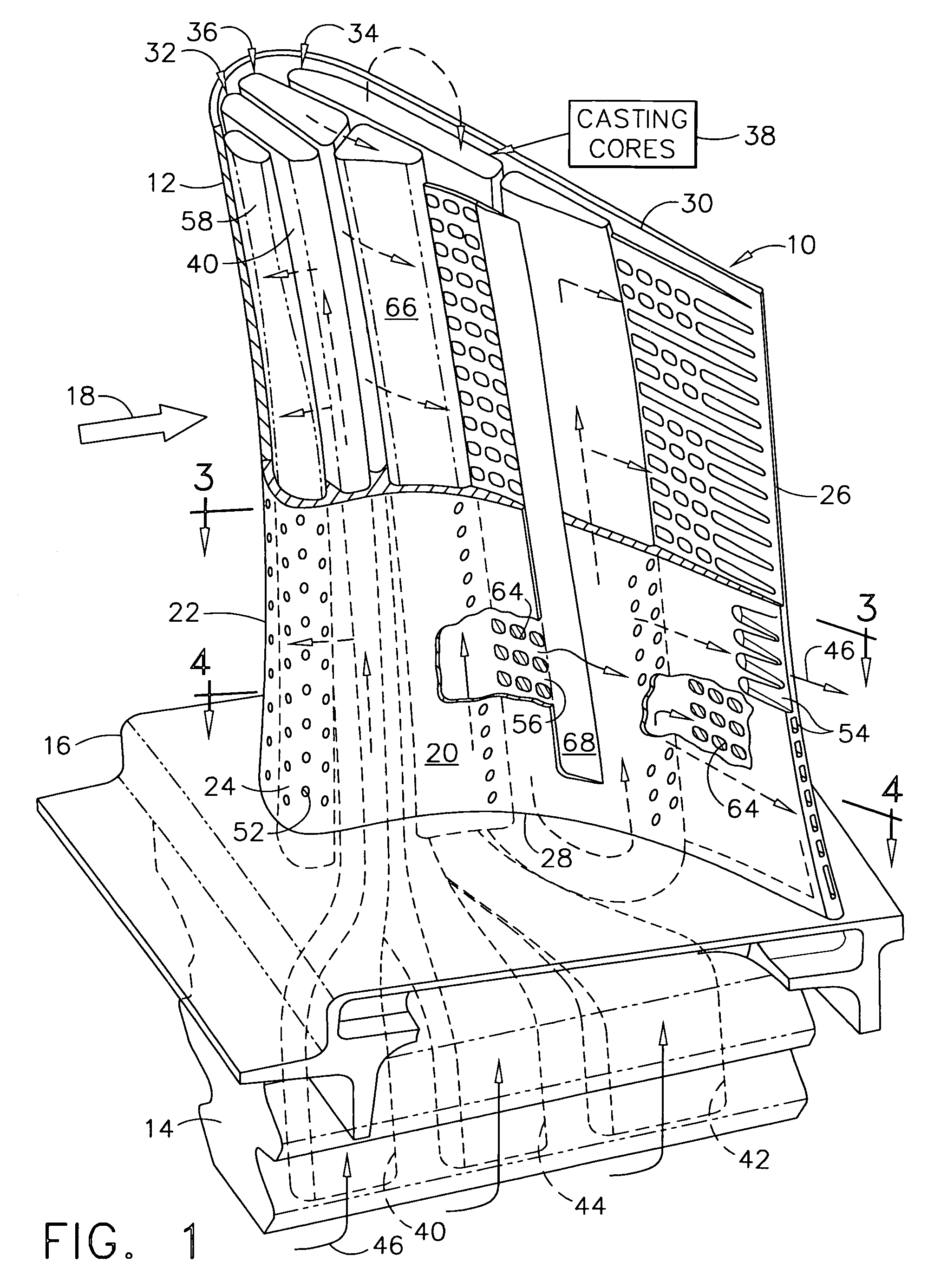
[0025]Illustrated in FIG. 1 is a first stage turbine rotor blade 10 for use in the high pressure turbine (HPT) of a gas turbine engine, such as a turbofan aircraft engine. The blade includes an airfoil 12 integrally joined to a supporting dovetail 14 at a flow bounding platform 16 radially therebetween. The blade may be made by conventional casting methods using conventional superalloy materials, such as nickel or cobalt based metals.

[0026]The airfoil has a suitable aerodynamic profile for extracting energy from hot combustion gases 18 provided during operation from an annular combustor (not shown), and as guided by a conventional HPT turbine nozzle (not shown).

[0027]The platform 16 defines a portion of the inner flow boundary for the combustion gases. And, the dovetail 14 has a typical lobed configuration for being retained in a complementary dovetail slot in the perimeter of the supporting turbine rotor disk (not shown).

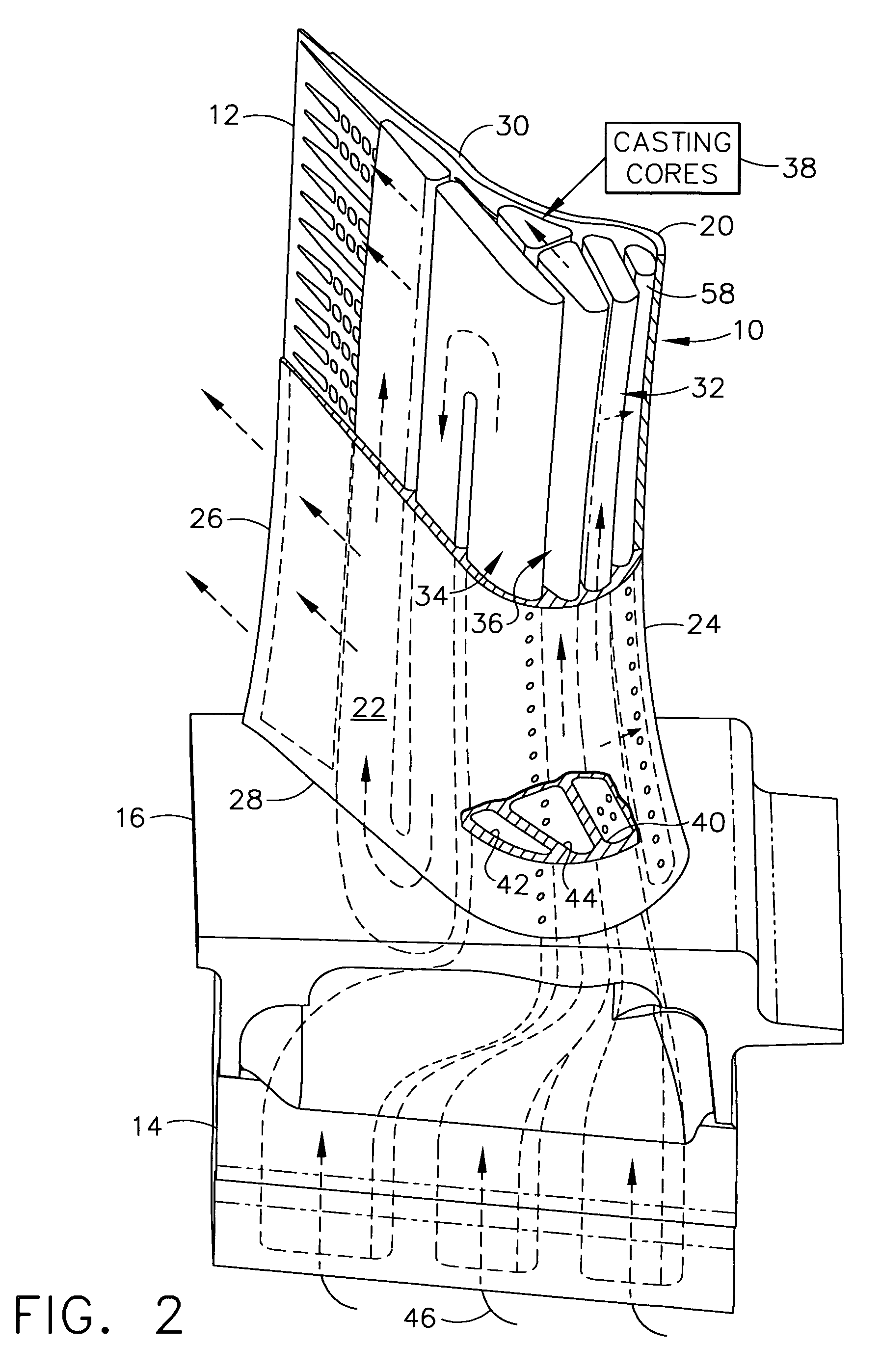
[0028]FIGS. 1 and 2 illustrate the circumferentially opposite...


PUM


Abstract

A turbine blade includes an airfoil having pressure and suction sidewalls extending between leading and trailing edges, and from root to tip. A dovetail is joined to the airfoil root at a platform. Three internal cooling circuits extend in span inside the airfoil, and each circuit includes a respective inlet channel commencing in axially adjacent alignment in the dovetail. The inlet channels twist together from the dovetail, through the platform, and into the airfoil behind the leading edge in transverse adjacent alignment across the sidewalls.

Description

[0001]The U.S. Government may have certain rights in this invention pursuant to contract number F33615-02-C-2212 awarded by the U.S. Department of the Air Force.BACKGROUND OF THE INVENTION[0002]The present invention relates generally to gas turbine engines, and, more specifically, to turbine blade cooling therein.[0003]In a gas turbine engine air is pressurized in a compressor and mixed with fuel in a combustor for generating hot combustion gases. Turbines are used to extract energy from the gases and power the compressor while producing useful output power such as driving an upstream fan in an aircraft turbofan gas turbine engine application.[0004]Engine efficiency may be maximized by maximizing the temperature of the combustion gases, but the high combustion gas temperature will limit the useful life of the various turbine components exposed to the combustion gases during operation.[0005]The first stage turbine rotor blade receives the hottest combustion gases from the upstream tu...

Claims


Application Information

Patent Timeline
Patent Type & Authority Patents(United States)
IPC IPC(8): F03D11/00F01D5/18F02C7/18
CPCF01D5/187Y02T50/676Y02T50/673Y02T50/60
Inventor LEE, CHING-PANGBRASSFIELD, STEVEN ROBERTPRAKASH, CHANDER
Owner GENERAL ELECTRIC CO
Learn More