Variable vane arm/unison ring attachment system

a technology of unison ring and attachment system, which is applied in the direction of machines/engines, stators, liquid fuel engines, etc., can solve the problems of wear at the mating surface, and achieve the effect of minimizing the potential for relative vibration, reducing the bearing area, and minimizing wear

Inactive Publication Date: 2006-01-10
RTX CORP
View PDF5 Cites 34 Cited by
  • Summary
  • Abstract
  • Description
  • Claims
  • Application Information

AI Technical Summary

Benefits of technology

[0006]Accordingly, it is an object of the present invention to provide an improved attachment system for attaching a vane arm to a unison ring and to a variable vane spindle.
[0008]It is still a further object of the present invention to provide an attachment system as above which has an increased bearing area to minimize wear.
[0009]It is yet a further object of the present invention to provide an attachment system as above which minimizes the potential for relative vibration at the joint interface.
[0010]It is yet another object of the present invention to provide an attachment system as above which creates damping and eliminates joint slop / hysteresis.
[0013]The present invention also relates to a vane arm having an arm portion and a bushing connected to the arm portion. The arm portion has a thickness and the bushing has a height which is maximized to fit within a cross section of the unison ring with a clearance between top and bottom surfaces of the bushing sufficient to eliminate any potential for contact and subsequent wear of the top and bottom surfaces.

Problems solved by technology

The current vane arm / unison ring attachment system suffers from a number of deficiencies including wear between the pin and vane arm bushing, a potential for relative vibration at the joint interface between the pin 16 and the unison ring 15, and slop at the inner diameter of the unison ring 15 which causes wear at the mating surface.

Method used


Image

  • Variable vane arm/unison ring attachment system
  • Variable vane arm/unison ring attachment system
  • Variable vane arm/unison ring attachment system

Examples


Embodiment Construction

)

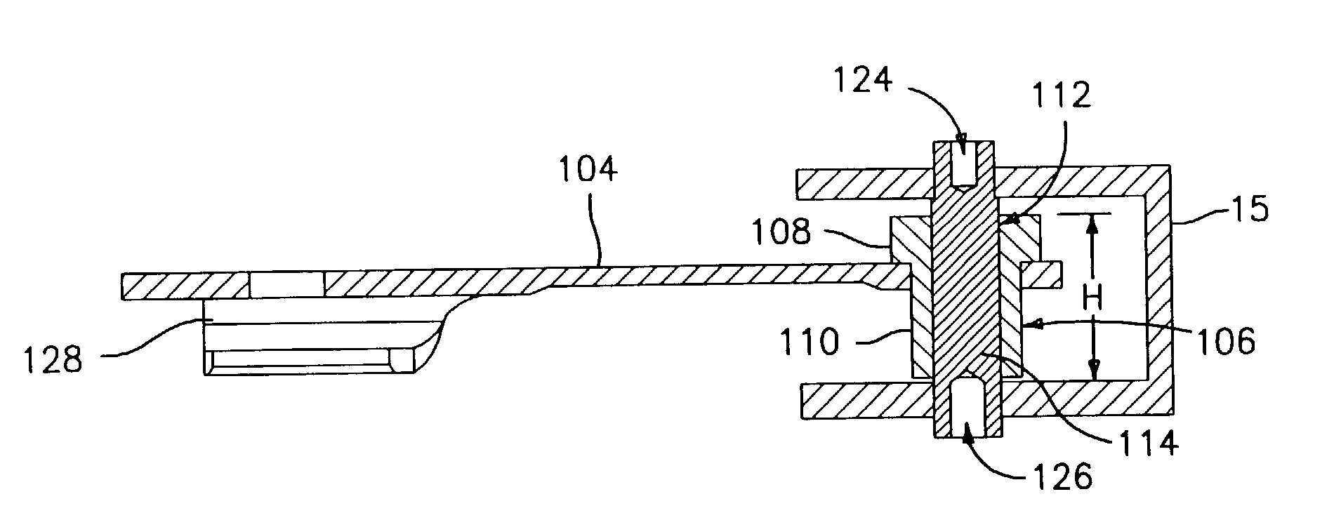
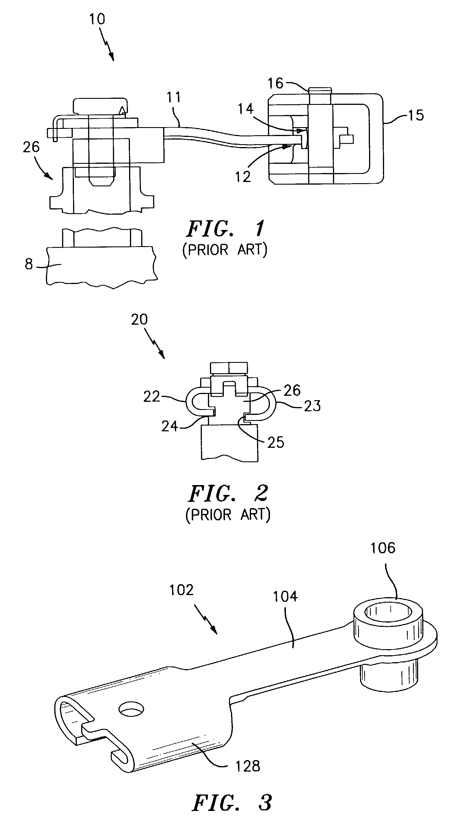
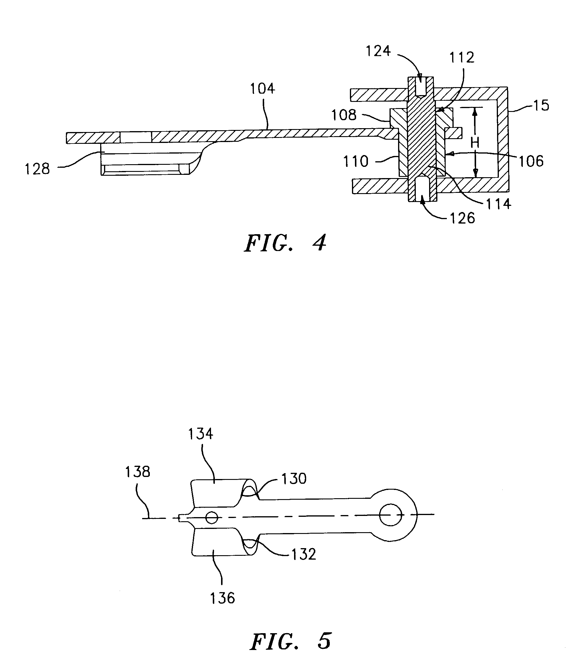
[0021]Referring now to the drawings, FIGS. 3–6 illustrates an improved vane arm 102 in accordance with the present invention for use in an attachment system 10 used in a variable incidence vane system within a gas turbine engine. The vane arm 102 is used to join a vane spindle 26 and a unison ring 15.

[0022]As shown in FIGS. 3 and 6, the vane arm 102 has an arm portion 104 with a thickness T. The arm portion 104 may be formed from any suitable material known in the art such as a nickel based alloy. A suitable nickel based alloy which may be used to form the arm portion 104 is Inconel 718.

[0023]The vane arm 102 also has a bushing 106 connected to it. In a preferred construction, the bushing 106 is joined to the vane arm 102 by brazing using any suitable brazing material such as a gold based alloy or a nickel based alloy. The bushing 106 may also be formed from a nickel based alloy such as Inconel 718. It may also be formed from any other suitable metallic material known in the art. W...


PUM


Abstract

An attachment system for use with a variable incidence vane is disclosed. The attachment system includes a vane arm for joining a unison ring to a vane spindle. The vane arm has an arm portion and a bushing connected to the arm portion. The attachment system further has a pin for joining the vane arm to the unison ring. The pin fits within an interior bore in the bushing and is joined to the unison ring by a dual swage.

Description

BACKGROUND OF THE INVENTION[0001]The present invention relates to a variable vane arm / unison ring / vane attachment system for use in a variable incidence vane system in a gas turbine engine.[0002]A variable vane arm 11 is used to control the incidence angle of vanes 8 in the compressor section of gas turbine engines. The vanes 8 are arranged as a stage set around the circumference of the compressor. The vane arm 11 attaches to each vane spindle 26 which rotates in a bearing mounted in the compressor case. The set of vanes 8 in a stage are actuated by a circumferential synchronizing or unison ring 15 that rotates about the engine axis. The vane arm 11 imparts motion from the synchronizing ring 15 to the vane spindle 26 and has to accommodate all the relative motion between the ring 15 and the vane 8.[0003]A current vane arm / unison ring attachment system 10 is illustrated in FIG. 1. The vane arm 11 used therein incorporates a brazed bushing 12 which has chamfered reliefs 14 to allow fo...

Claims


Application Information

Patent Timeline
Patent Type & Authority Patents(United States)
IPC IPC(8): F04D29/56F01D17/16
CPCF01D17/162F05D2260/79F05D2250/292F05D2230/64F05D2260/50
Inventor ALEXANDER, PHILLIPPICKENS, JOHN
Owner RTX CORP
Why Eureka
Try Eureka