Method and apparatus for delivering a colonic lavage

Inactive Publication Date: 2006-01-10
JANE S ABELL TRUSTEE U A DATED 09 17 2014 +1
View PDF31 Cites 43 Cited by
  • Summary
  • Abstract
  • Description
  • Claims
  • Application Information

AI Technical Summary

Benefits of technology

[0028]An additional object of the invention is to provide a lightweight, portable, easy to use colonic lavage apparatus that can be carried to and/or used by a patient in his home rather that requiring the patient to travel to a

Problems solved by technology

Valves used in colonic lavage systems and, indeed, in other medical applications, are subject to a number of relatively severe operational constraints.
In addition, the valves must be gentle in that they must open and close in such a way that fluid flow is not stopped or started abruptly, which can shock a patient's system or damage delicate tissues.
This is particularly true in the case of colonic lavage procedures because colon walls are thin and subject to rupture under abrupt stresses.
For example, the valve is relatively expensive to manufacture because key components are injection molded.
Further, the valve is time consuming and thus expensive to fabricate because the internal flexible tube must be installed manually and the end caps and other components must be glued to the chamber by hand.
The hard plastic shell of the chamber can shatter if dropped and is uncomfortable to the skin of a patient such that the valve cannot comfortably be laid or rested on the patient during use.
Finally, since the flexible internal tube of the valve is separate and made of a different material than other valve components, it can, under certain circumstances, come loose from the couplers within the valve causing the valve to fail and risking contamination of the compressed air supply.
For these reasons, and particularly due to the expense of production and fabrication, conventional pneumatic sphincter valves have not been economical for use with disposable colonic lavage kits designed to be discarded after a single use.
Accordingly, such disposable kits have been expensive and thus not easily available to lower income persons or patients on fixed incomes.
However, the devices of these patents are also burdened with various problems and shortcomings inhere

Method used


Image

  • Method and apparatus for delivering a colonic lavage
  • Method and apparatus for delivering a colonic lavage
  • Method and apparatus for delivering a colonic lavage

Examples


Embodiment Construction

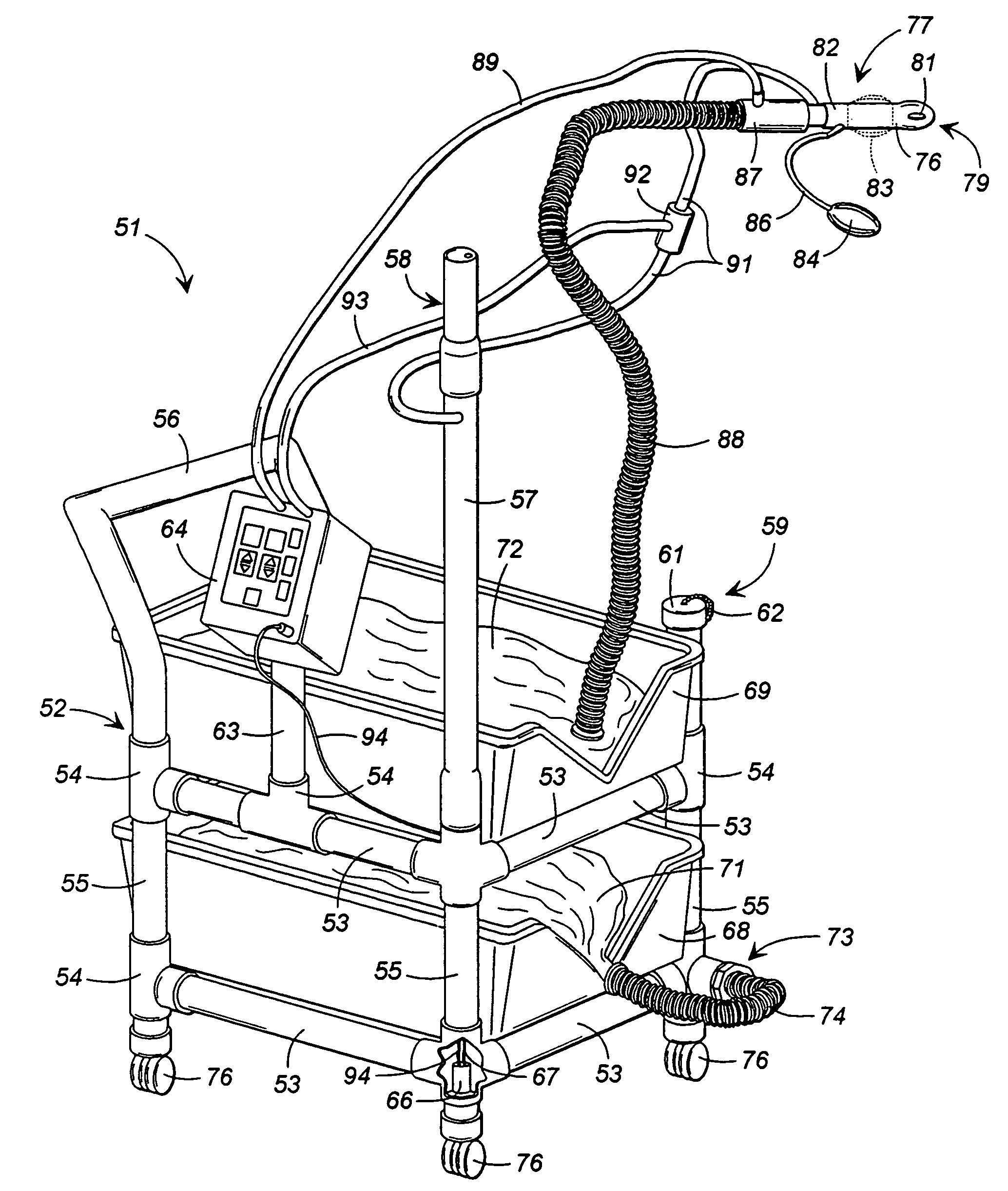
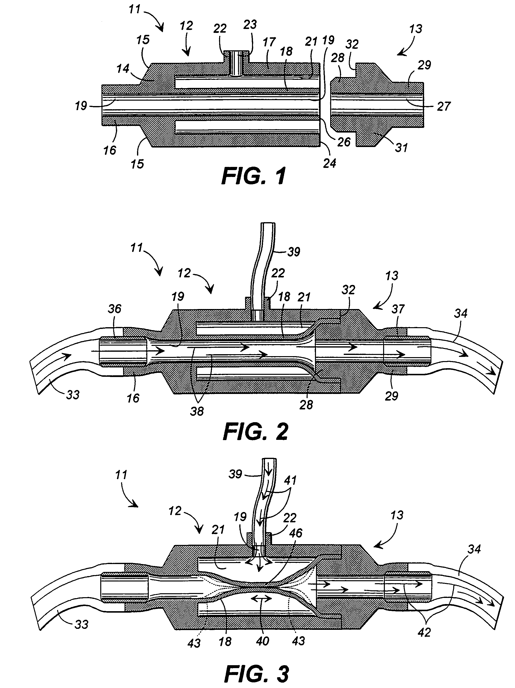
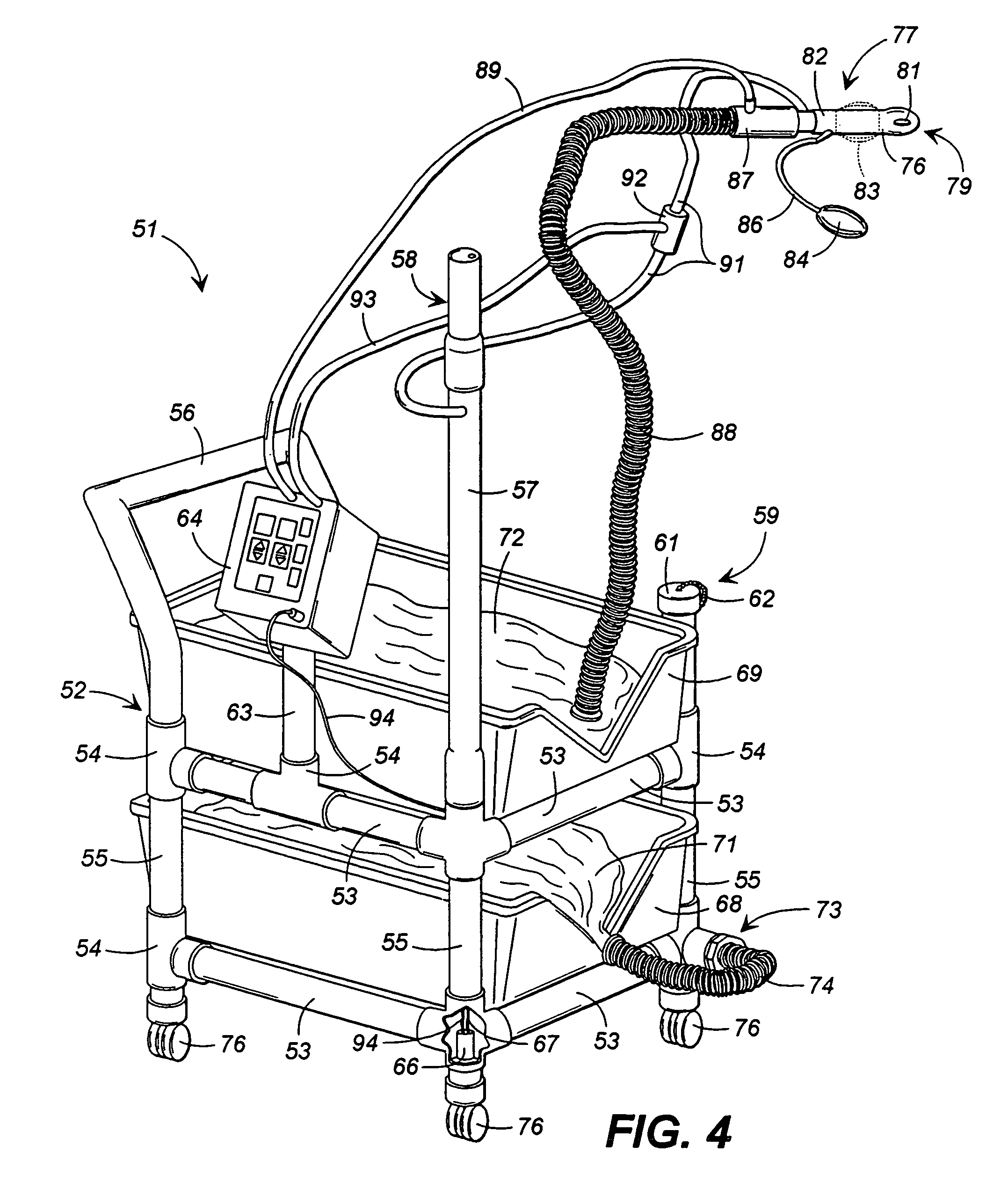
[0041]Referring now to the drawings, wherein like numerals refer to like parts throughout the several views, FIG. 1 illustrates in cross-section a sphincter valve assembly that embodies principles of the present invention in a preferred form. The sphincter valve assembly of FIGS. 1 through 4 are particularly suitable for use in the colonic lavage method and apparatus of this invention. The assembly 11 comprises two components, a main body 12 and an end cap 13. Both the main body 12 and the end cap 13 preferably are molded at the same time and in a common mold. Further, both components in the preferred embodiment are formed of a flexible somewhat rubber like material such as, for example, a silicone, a silicone rubber compound, or another synthetic rubber material. Latex materials can also be used, but they are not preferred for applications where the valve is likely to come into contact with a patient's skin because many patients have latex allergies. In any event, the material can ...


PUM


Abstract

A method of providing a colonic lavage includes the steps of delivering a predetermined volume of lavage liquid to the colon to fill the colon with lavage liquid to a predetermined level, substantially maintaining the predetermined level of lavage liquid within the colon for a predetermined time in a hold cycle to hydrate impacted material within the colon, inducing a pulsed motion of the lavage liquid within the colon during the hold cycle to enhance hydration and break up of impacted material within the colon and to induce peristaltic activity of the colon, and draining lavage liquid from the colon. The step of inducing pulsed motion of the lavage liquid within the colon may be accomplished through an inverse pulsed technique or a pulsed hold technique.

Description

REFERENCE TO RELATED APPLICATION[0001]This application is a continuation-in-part of U.S. patent application Ser. No. 09 / 031,225, filed Feb. 26, 1998, now U.S. Pat. No. 6,106,506; a continuation-in-part of U.S. patent application Ser. No. 08 / 811,816 filed Mar. 4, 1997, now U.S. Pat. No. 6,138,984.TECHNICAL FIELD[0002]This invention relates generally to devices and methods of delivering a colonic lavage and to pneumatically or hydraulically controllable sphincter valves usable in such devices and methods.BACKGROUND OF THE INVENTION[0003]In a variety of medical applications, valves are used to control the inflow and outflow of fluids into and out of a patient's body. Such applications include, among others, blood transfusions, stomach evacuations, heart lung machine procedures, and colonic lavage for the removal of fecal impactions from a patient's bowels and removal of fecal material during normal bowel maintenance programs. In the case of colonic lavage, it is common that a first val...

Claims


Application Information

Patent Timeline
IPC IPC(8): A61M31/00A61M3/02A61M39/22F16K7/07
CPCA61M3/0258F16K7/07A61M3/02A61M3/0275A61M39/228A61M2210/1064A61M3/0283A61M3/0208A61M3/0216A61M2205/50
Inventor ABELL, ROYHARDY, MICHAEL C.
Owner JANE S ABELL TRUSTEE U A DATED 09 17 2014
Why Eureka
Try Eureka