Redundantly constrained laminar structure as weak-link mechanisms

a weak link mechanism and redundant constraint technology, applied in mechanical equipment, transportation and packaging, chemical equipment and processes, etc., can solve the problems of unstable structure, difficult to achieve the desired precision, and single layer structures that normally do not have the desired stiffness against flexing, etc., to achieve the desired stiffness and stability

Inactive Publication Date: 2006-01-10
UCHICAGO ARGONNE LLC
View PDF10 Cites 9 Cited by
  • Summary
  • Abstract
  • Description
  • Claims
  • Application Information

AI Technical Summary

Benefits of technology

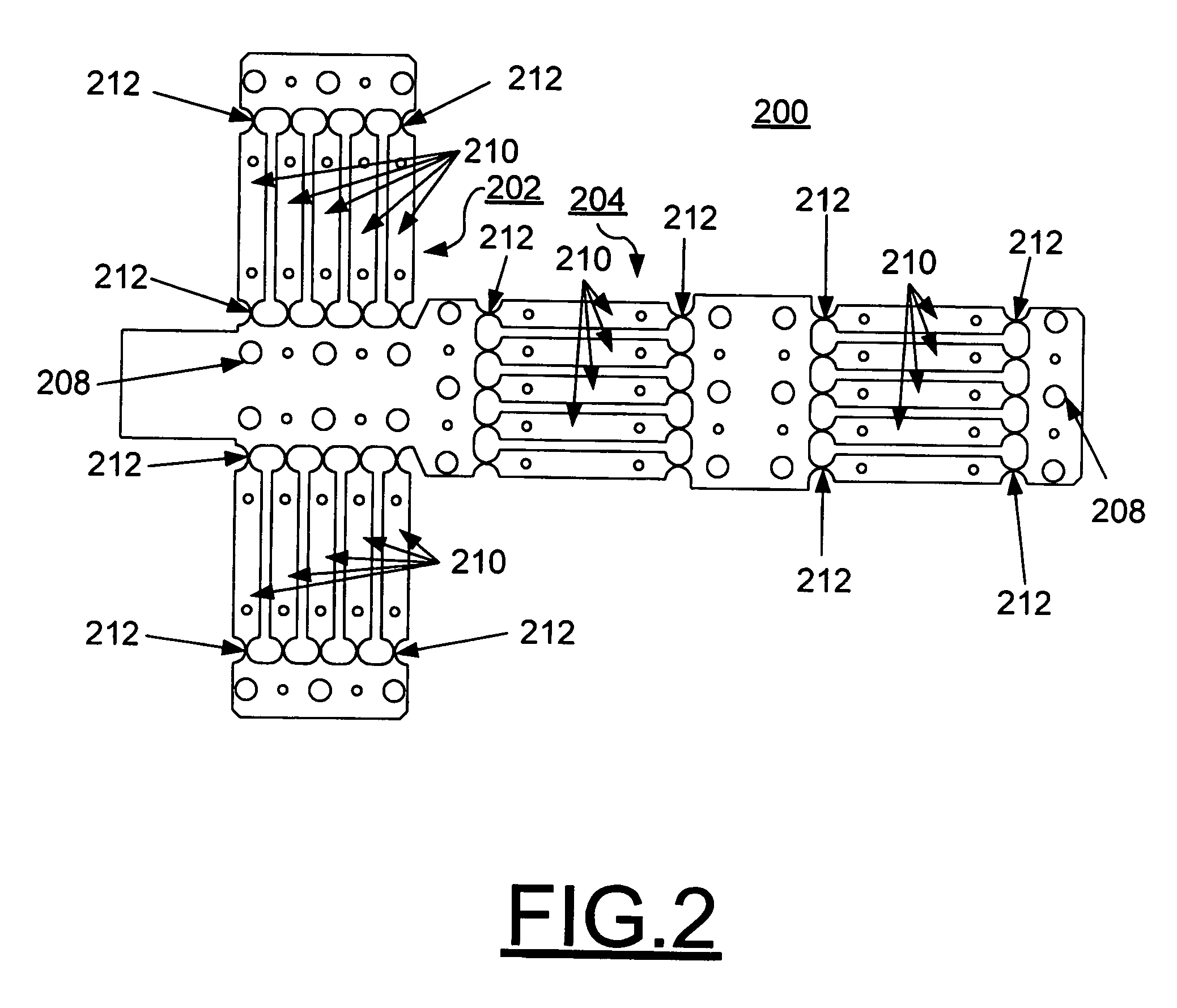
[0014]The redundantly constrained laminar structures as weak-link mechanisms of the invention include a stack of a plurality of thin material structures. The stack of structures forming a laminar structure include multiple weak-link connections providing controllable movements in a plane of the layer and having a desired stiffness and stability.

Problems solved by technology

This is expensive and difficult to achieve the desired precision.
These single layer structures do not normally have the desired stiffness against flexing.
In addition, the limitation of two connecting links is a factor in the instability of the structure during the small movements.

Method used


Image

  • Redundantly constrained laminar structure as weak-link mechanisms
  • Redundantly constrained laminar structure as weak-link mechanisms
  • Redundantly constrained laminar structure as weak-link mechanisms

Examples


Embodiment Construction

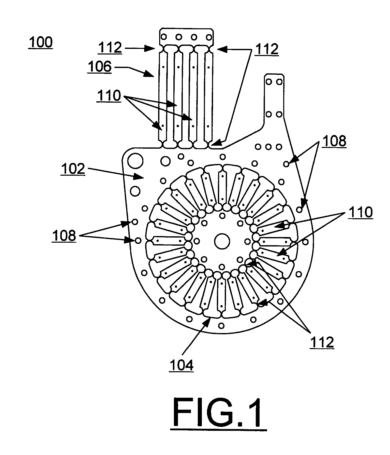
[0021]Having reference now to the drawings, in FIG. 1 there is shown an exemplary redundantly constrained weak-link structure in accordance with the preferred embodiment generally designated by the reference character 100. FIG. 1 shows the shape of the metal weak-link sheet 102, which is produced by a photochemical machining process. Two motion structures 104, 106 are designed on the same metal sheet 102. A wheel-shaped weak-link group 104 acts as a planar rotary shaft, and a parallelogram-shaped weak-link group 106 acts as a linear slide. To optimize the system stiffness, over-constrained mechanisms were chosen in this design of weak-link structure 100. The precision of the modern photochemical machining process using lithography techniques makes it possible to construct a strain-free, or strain-limited, over-constrained mechanism on the thin metal sheet 102. By stacking these thin metal weak-link sheets 102 with align-pins, a solid complex weak-link structure is constructed for a ...


PUM

PropertyMeasurementUnit
yield stressaaaaaaaaaa
structuresaaaaaaaaaa
stiffnessaaaaaaaaaa

Abstract

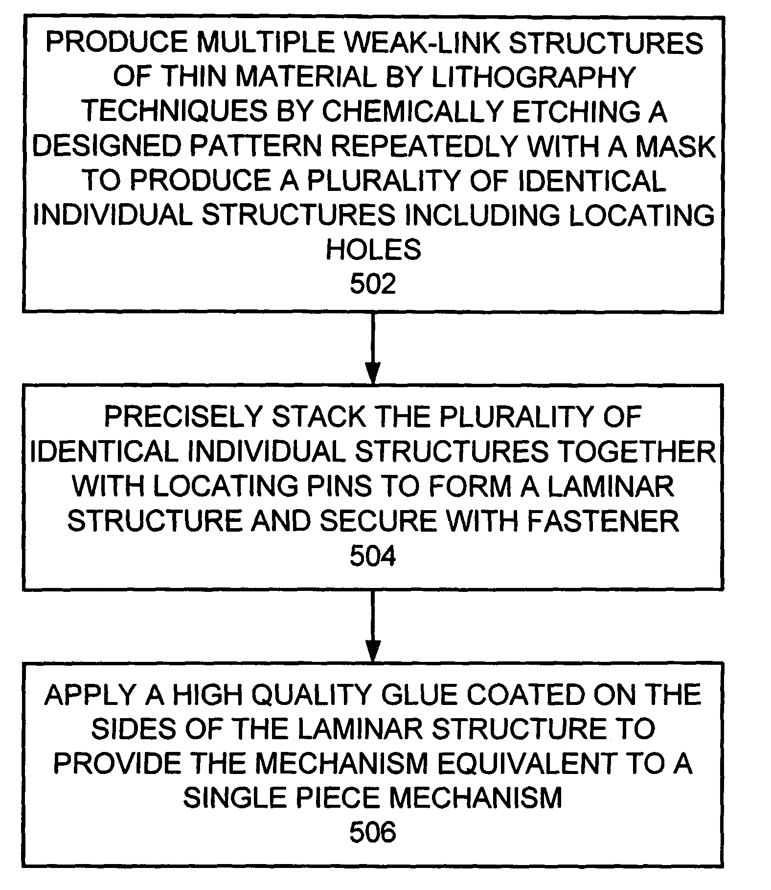
Redundantly constrained laminar structures as weak-link mechanisms and a novel method for manufacturing the redundantly constrained laminar structures as weak-link mechanisms are provided. The method for producing the redundantly constrained laminar structures as weak-link mechanisms is carried out by lithographic techniques. A designed pattern is repeatedly chemically etched with a mask to produce a plurality of individual identical units. The units are stacked together to form the laminar structure and are secured together with fasteners. A high quality adhesive can be applied to the sides of the laminar structure to provide the mechanism equivalent to a single piece mechanism. The redundantly constrained laminar structures as weak-link mechanisms of the invention include a stack of a plurality of thin material structures. The stack of structures forming a laminar structure include multiple weak-link connections providing controllable movements in a plane of the layer and having a desired stiffness and stability. The plurality of thin material structures include predetermined locating-holes used with locating-pins to precisely stack the thin material structures together and are used with fasteners to secure the stack together.

Description

[0001]This application is a divisional application of Ser. No. 09 / 930,699 filed on Aug. 15, 2001, now, U.S. Pat. No. 6,607,840.[0002]This application claims the benefit of prior filed copending provisional application filed Oct. 11, 2000, by Deming Shu, Thomas S. Toellner, and Esen E. Alp, provisional application Ser. No. 60 / 239,599 and entitled REDUNDANTLY CONSTRAINED LAMINAR STRUCTURE AS WEAK-LINK MECHANISMS. The subject matter of the above-identified copending provisional application is incorporated herein by reference.CONTRACTUAL ORIGIN OF THE INVENTION[0003]The United States Government has rights in this invention pursuant to Contract No. W-31-109-ENG-38 between the United States Government and Argonne National Laboratory.FIELD OF THE INVENTION[0004]The present invention relates to a novel weak-link mechanism with redundant constrained structure, and more particularly, relates to redundantly constrained laminar structures as weak-link mechanisms and a novel method for manufactu...

Claims


Application Information

Patent Timeline
Patent Type & Authority Patents(United States)
IPC IPC(8): C03C15/00B32B3/10
CPCB32B3/10Y10T428/12188Y10T428/12528Y10T428/12653Y10T428/12326
Inventor SHU, DEMINGTOELLNER, THOMAS S.ALP, E. ERCAN
Owner UCHICAGO ARGONNE LLC
Why Eureka
Try Eureka