Current sensor and overload current protective device therewith

a technology of overload current and current sensor, which is applied in the field of current sensors, can solve the problems of large sensor units, and insufficient current detection rang

Inactive Publication Date: 2006-01-10
FUJI ELECTRIC FA COMPONENTS & SYST CO LTD
View PDF11 Cites 18 Cited by
  • Summary
  • Abstract
  • Description
  • Claims
  • Application Information

AI Technical Summary

Benefits of technology

[0013]To solve the above-mentioned problems, one embodiment of the invention includes: two magnetic detection elements which has a magnetic impedance effect and is provided near the wiring leading a current; a current applying unit for applying an alternating current to both ends of the magnetic detection element; a DC bias magnetic field applying unit for applying a DC bias magnetic field to the magnetic detection element; two detection units for detecting the variations in magnetic field by a current from t

Problems solved by technology

Conventionally, a current transformer has been widely used as a current sensor, but its low sensitivity requires a laminated iron core, and the iron core generates magnetic saturation, thereby causing the problem of an insufficient current detection range.
The iron core also causes the problem of a large sensor unit.
Like the current transformer, the above-mentioned method of using the magnet gathering core uses a core of at least 3˜4 cm and requires a large sensor unit, and generates the magnetic saturation by the iron core, thereby obtaining an insufficient current detection range.
Furthermore, using a wire type or a thin film type magnetic impedance element, ther

Method used


Image

  • Current sensor and overload current protective device therewith
  • Current sensor and overload current protective device therewith
  • Current sensor and overload current protective device therewith

Examples


first embodiment

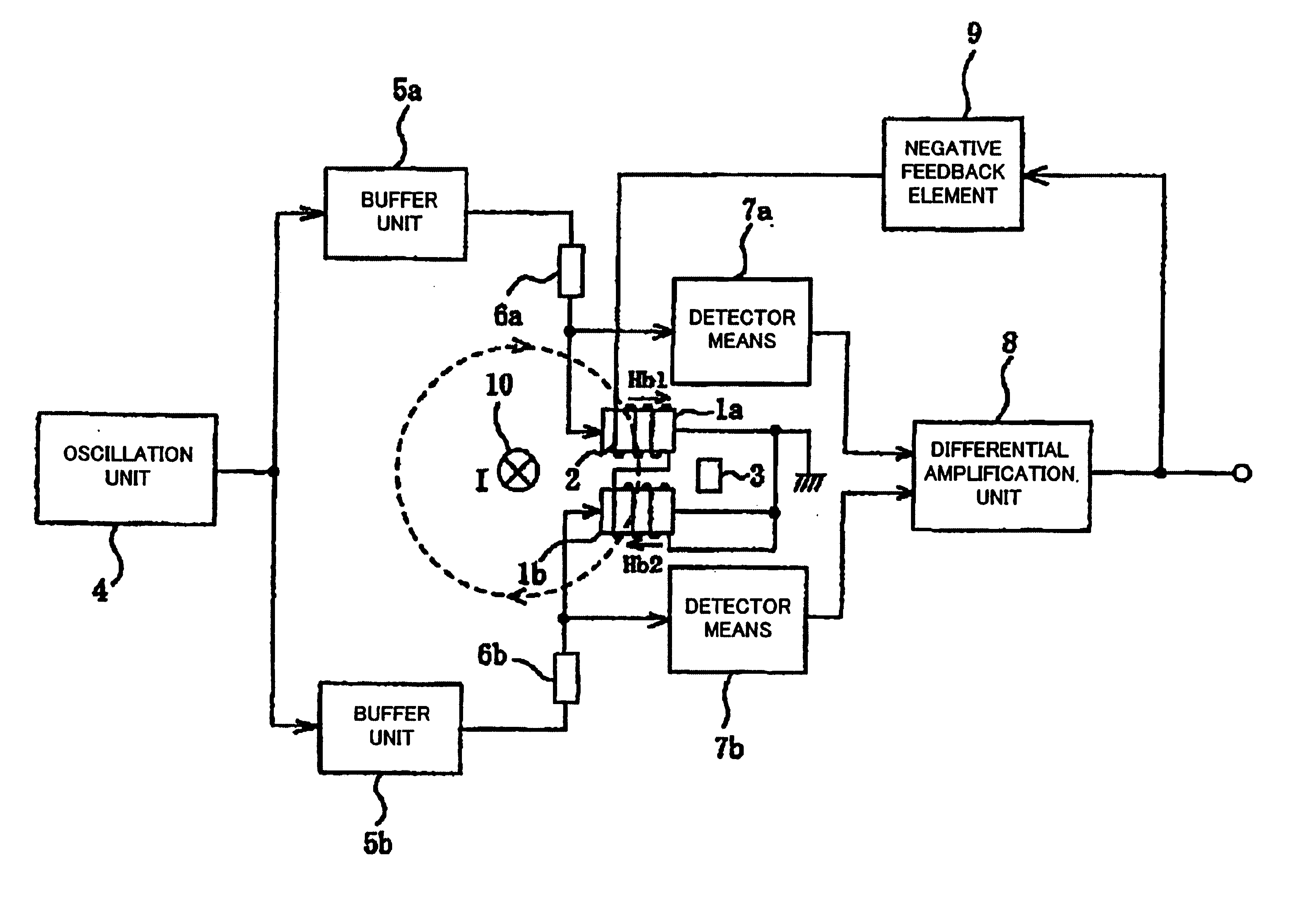
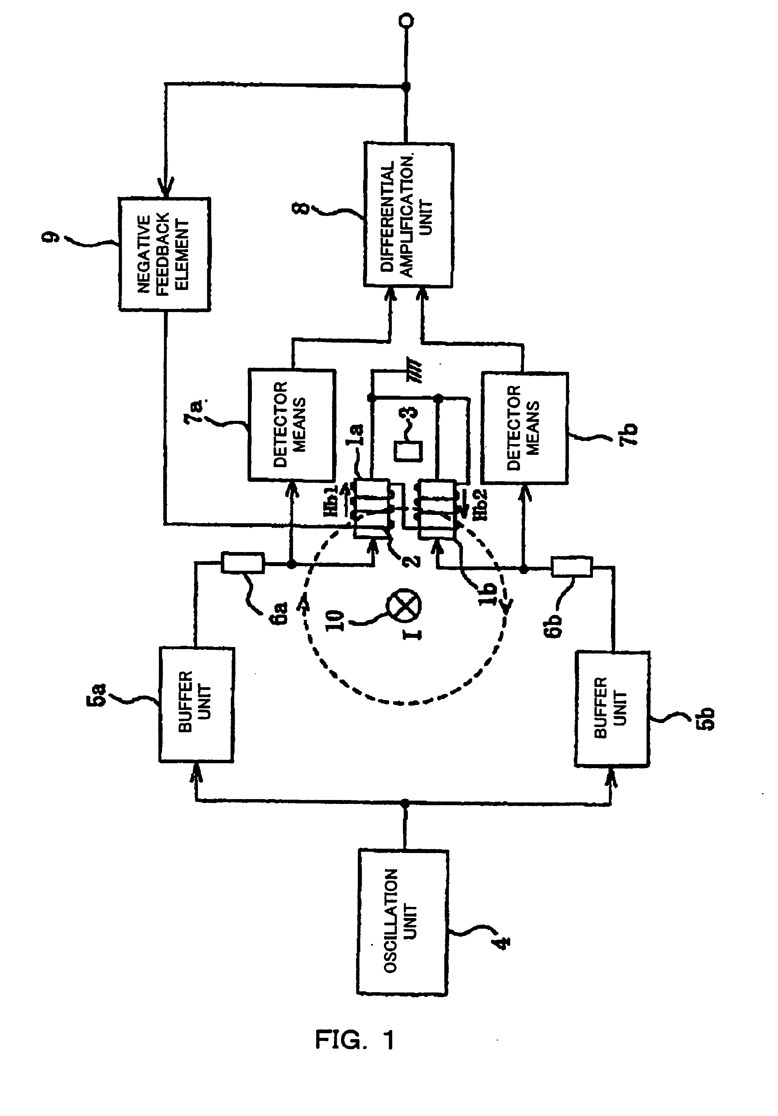
[0039]FIG. 1 shows the configuration of the present invention.

[0040]In FIG. 1, magnetic impedance elements (also referred to simply as MI elements) 1a and 1b can be wire-shaped or thin-film-shaped. A compensation coil 2 applies negative feedback to the MI elements 1a and 1b. A magnet 3 applies a DC bias to the MI elements 1a and 1b. An oscillation unit 4 applies a DC current to the MI elements 1a and 1b. Buffer units 5a and 5b are inserted depending on the level of the current output by the oscillation unit 4. Reference numerals 6a and 6b denote resistors. Detector means 7a and 7b detect the variations in alternating current depending on the external magnetic field applied to the MI elements 1a and 1b. A differential amplification unit 8 amplifies the differential of the output of the detection unit. A negative feedback element 9 supplies a current to the compensation coil 2 depending on the output of the differential amplification unit 8. Wiring 10 leads a detection current.

[0041]A...

second embodiment

[0047]FIG. 3 shows the configuration of the present invention.

[0048]In FIG. 3, a constant current unit 91, a switch unit 92, an analog-digital conversion unit 81, and an arithmetic control unit 82 configured by a microcomputer, etc. are added to the configuration shown in FIG. 1.

[0049]With the above-mentioned configuration, a magnetic field is applied to the output of the differential amplification unit 8 using the compensation coil 2 and the negative feedback element 9 in the direction of decreasing the output of the differential amplification unit 8. The arithmetic control unit 82 controls the switch unit 92 to apply a constant current from the constant current unit 91 to the compensation coil 2, and controls the analog-digital conversion unit 81 to detect the output of the differential amplification unit 8. The arithmetic control unit 82 controls the output obtained when a constant current is applied under a predetermined condition to be stored as a reference value, thereby compa...

third embodiment

[0054]FIG. 5 shows the configuration of the present invention.

[0055]As clearly shown in FIG. 5, the example is characterized by the two negative feedback elements 9a and 9b. In this example, the negative feedback elements 9a and 9b and the compensation coil 2 apply a magnetic field to the MI elements 1a and 1b in the direction of decreasing the output of the differential amplification unit 8 depending on the output of the differential amplification unit 8. Since the negative feedback elements 9a and 9b are normally configured by resistors as describe above, the output sensitivity to the detected current can be decreased proportional to the resistance. Therefore, the values of the negative feedback elements 9a and 9b are set depending on the measurement range, and the switch unit 92 automatically switches the values based on the output of the differential amplification unit 8, thereby obtaining a high-precision current detection characteristic in a wide measurement range.

[0056]In FIG...


PUM


Abstract

A small, low-cost, wide-range current sensor excellent in environmental resistance and noise resistance and high in accuracy, and an application device, a DC magnetic field is applied to two magnetic elements (1a, 1b) having a magnetic impedance effect by means of a magnet (3), while a negative feedback magnetic field is applied to both elements by means of a coil (2). The variation of the magnetic field depending on the external magnetic field applied to the magnetic elements (1a, 1b) is detected by detection units (7a, 7b). The difference between the output is amplified by a differential amplifier unit (8). Thus, detection is achieved in a wide range while eliminating the influence of the noise.

Description

TECHNICAL FIELD[0001]The present invention relates to a current sensor using a magnetic element having a magnetic impedance effect, and an overload current protective device for use with the current sensor.BACKGROUND ART[0002]Conventionally, a current transformer has been widely used as a current sensor, but its low sensitivity requires a laminated iron core, and the iron core generates magnetic saturation, thereby causing the problem of an insufficient current detection range. The iron core also causes the problem of a large sensor unit.[0003]On the other hand, there is a method in which a Hall element and a magnetoresistive element are used as current detection elements. However, since they are low in detection sensitivity, the sensitivity is commonly improved by providing a magnet gathering core and a Hall element or a magnetic element mounted at the gain of the magnet gathering core.[0004]Like the current transformer, the above-mentioned method of using the magnet gathering core...

Claims


Application Information

Patent Timeline
IPC IPC(8): G01R31/28G01R15/14G01R33/02G01R15/18G01R15/20G01R19/165G01R33/028
CPCG01R15/18G01R15/148
Inventor KUDO, TAKAHIROKITAIDE, YUJIROISHIKAWA, KIMITADA
Owner FUJI ELECTRIC FA COMPONENTS & SYST CO LTD
Why Eureka
Try Eureka