Position-sensing device for 3-D profilometers

a technology of profilometer and sensing device, which is applied in the direction of instruments, electrical equipment, geological measurements, etc., can solve the problems of affecting the speed of off-the-shelf profilometer, acquisition speed, image per second, processing capacity, etc., and achieves the effect of faster data acquisition speed

Inactive Publication Date: 2006-01-10
INSTITUT NATIONAL D'OPTIQUE
View PDF4 Cites 16 Cited by
  • Summary
  • Abstract
  • Description
  • Claims
  • Application Information

AI Technical Summary

Benefits of technology

[0009]It is a further aim of the present invention to provide a

Problems solved by technology

Among the design limitations affecting the speed of off-the-shelf profilometers are the acquisition speed, in images per second, of the digital camera, and the processing capacity of the data

Method used


Image

  • Position-sensing device for 3-D profilometers
  • Position-sensing device for 3-D profilometers
  • Position-sensing device for 3-D profilometers

Examples


Embodiment Construction

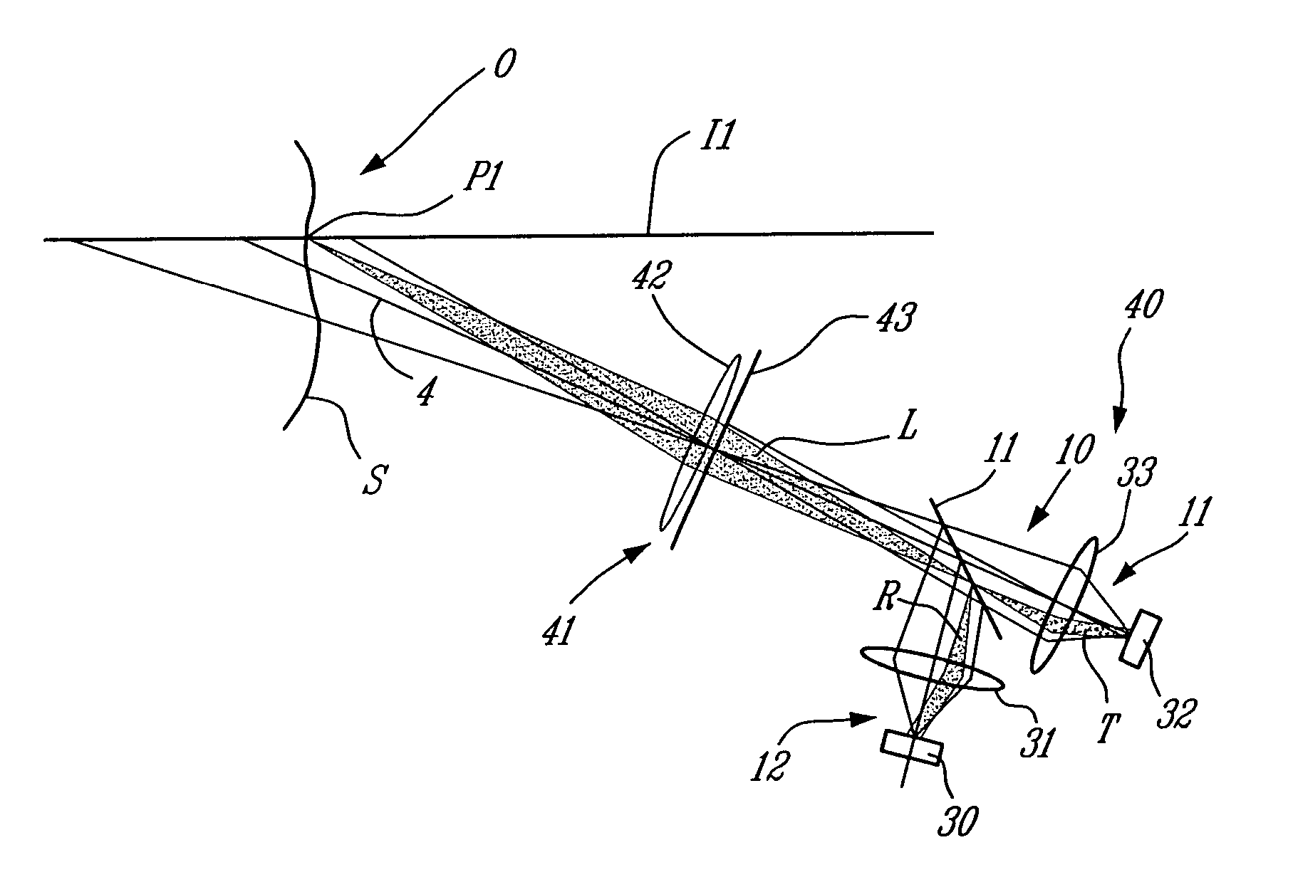
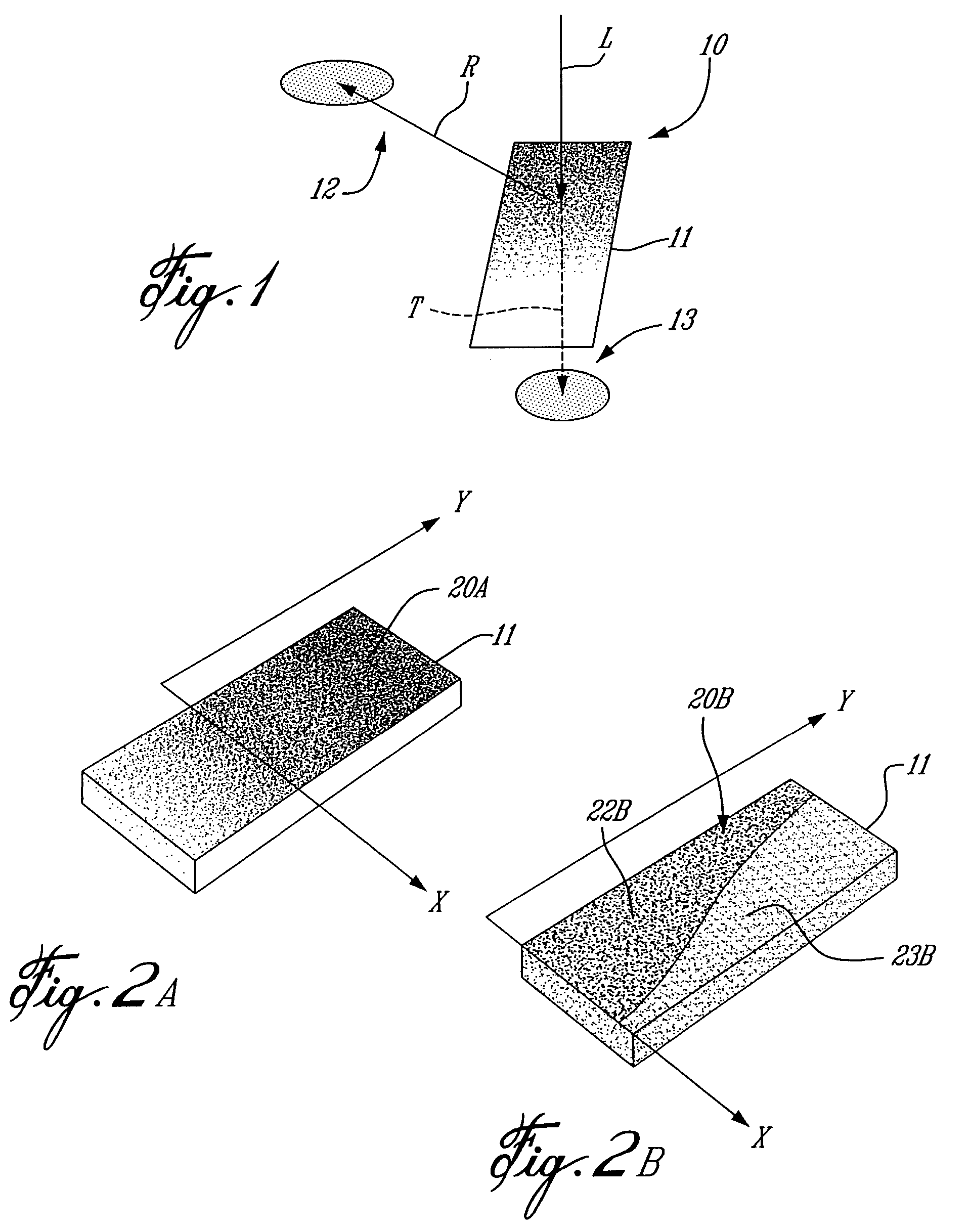
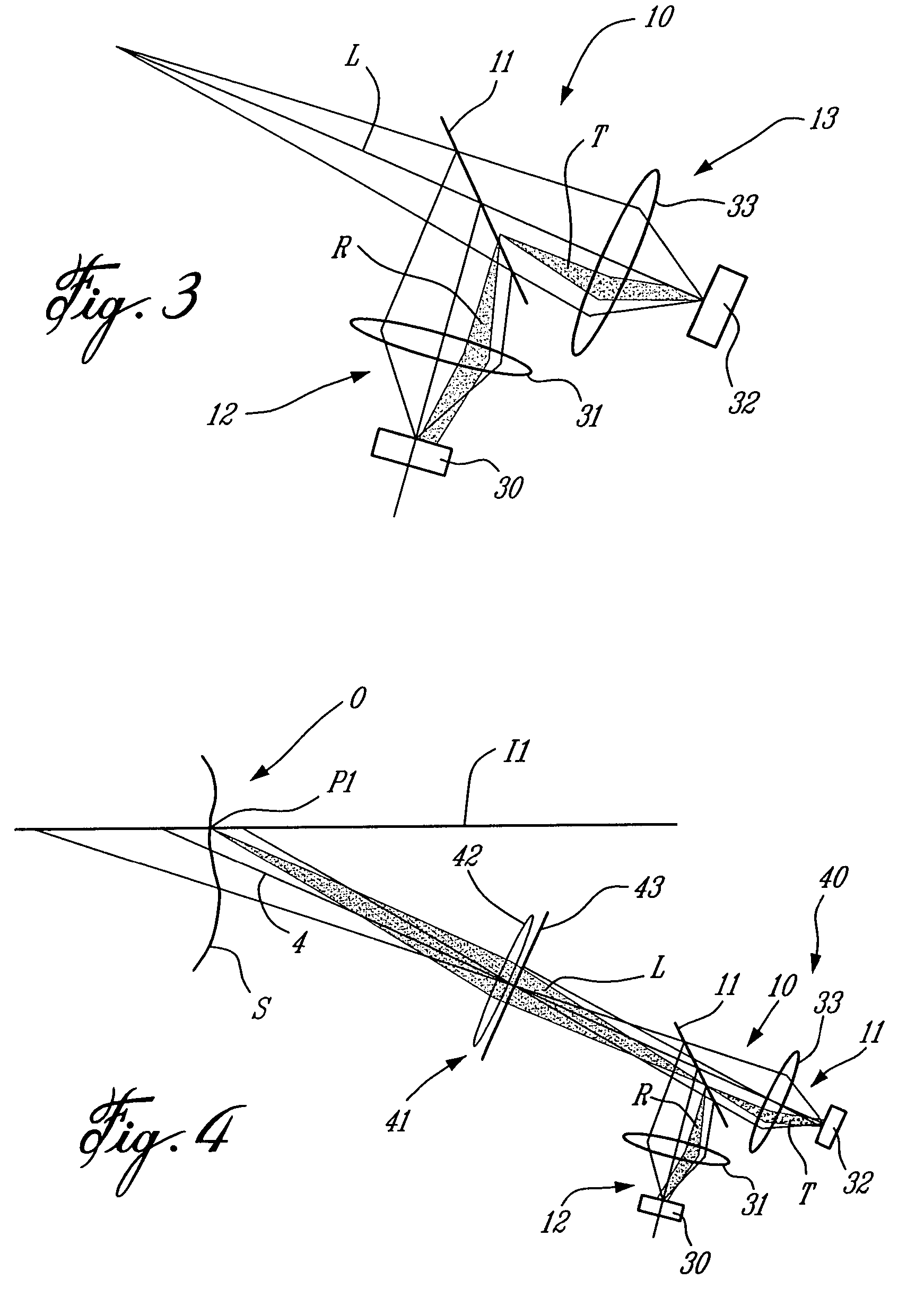
[0029]Referring to the drawings, and more particularly to FIG. 1, a position-sensing device in accordance with the present invention is generally shown at 10. The position-sensing device 10 has a beam splitter 11, a reflective photodetector section 12 and a transmission photodetector section 13. The position-sensing device 10 can be used as part of position-sensing apparatuses for obtaining 3-D profiles of objects. However, in a basic embodiment of the position-sensing device 10, the latter will be used to determine the distance separating it from points on an object. A light beam L being reflected from the object is received by the position-sensing device 10 More precisely, the light beam L from the surface of the object projects a spot of light on a surface of the beam splitter 11. A portion of the light beam L is reflected, whereby the beam will be referred to as “reflective channel R.” A remaining portion of the light beam L is transmitted through the beam splitter 11, whereby t...


PUM


Abstract

An apparatus for sensing position data of a light pattern created by a known light source on an object, comprising an optical system for collecting an incident light beam of the light pattern and transmitting the incident light beam to a beam splitter. The beam splitter has a known reflection/transmission ratio, such that the incident light beam from the light pattern received on the surface of the beam splitter results in a transmission channel, transmitted through the beam splitter, and a reflective channel, reflected from the beam splitter, with intensities of the transmission channel and the reflective channel varying as a function of a position of the incident light beam on the surface of the beam splitter. Detectors detect the intensities of the reflective channel and of the transmission channels. Dimensions of points of the light pattern on the object are calculable as a function of the intensity of the reflective channel and of the intensity of the transmission channel.

Description

BACKGROUND OF THE INVENTION[0001]1. Field of the Invention[0002]The present invention relates to position data acquisition and, more particularly, to a device and method to be used as part of position-sensing apparatuses.[0003]2. Description of the Prior Art[0004]In the field of information sensing, machine vision technologies provide valuable information about the environment and about specific objects of interest through close inspection. Known 3-D data acquisition systems have been provided using 3-D sensors based on the active triangulation principle. In such systems, a specific known and fixed pattern of illumination (i.e., structured illumination) is projected from a light source (e.g., laser) on an object to be measured, and the intersection of that emitted pattern is observed from a known and fixed oblique angle by a digital camera, having photodetection means such as a charged coupled device (CCD) array, whereby the position of the illuminated points on the object translate...

Claims


Application Information

Patent Timeline
IPC IPC(8): G01B11/24G01B11/02
CPCG01B11/24G01B11/026
Inventor DOUCET, MICHELBOULANGER, DENISLAURENT, JOHN
Owner INSTITUT NATIONAL D'OPTIQUE
Why Eureka
Try Eureka