Device and method for reducing delay jitter in data transmission

a technology of delay jitter and data transmission, applied in the field of delay jitter, can solve the problems of individual packet delay time, varying propagation delay time among, and the delay time required for these individual packets to reach the receiving terminal b>30/b>, and achieve the effect of shortening the total delay tim

Inactive Publication Date: 2006-01-10
NTT DOCOMO INC
View PDF7 Cites 17 Cited by
  • Summary
  • Abstract
  • Description
  • Claims
  • Application Information

AI Technical Summary

Benefits of technology

[0030]This invention is made for solving the above-mentioned problem and aims at providing a delay jitter reducing device capable of shortening the total delay time and a delay jitter reducing method thereof.

Problems solved by technology

In a network such as the Internet, however, even in a case where a plurality of packet are transmitted from an unchanged source node to an unchanged destination node, the propagation delay time for individual packets are not necessarily the same as one another, and the propagation delay time varies among packets.
However, as described already, propagation delay time required for these individual packets to reach the receiving terminal 30 is not fixed for each voice packet.
However, the destination terminal 30 is not capable of finding how much propagation delay time it has taken for each voice packet to reach the destination.
However, in a case where the delay time of the first voice packet is as long as the maximum delay time dmax, the total delay time T results in a long period of time two times the maximum delay time dmax.
Thus, it is unfavorable that the total delay time T becomes long for the sake of reducing delay jitter.

Method used


Image

  • Device and method for reducing delay jitter in data transmission
  • Device and method for reducing delay jitter in data transmission
  • Device and method for reducing delay jitter in data transmission

Examples


first embodiment

A. First Embodiment

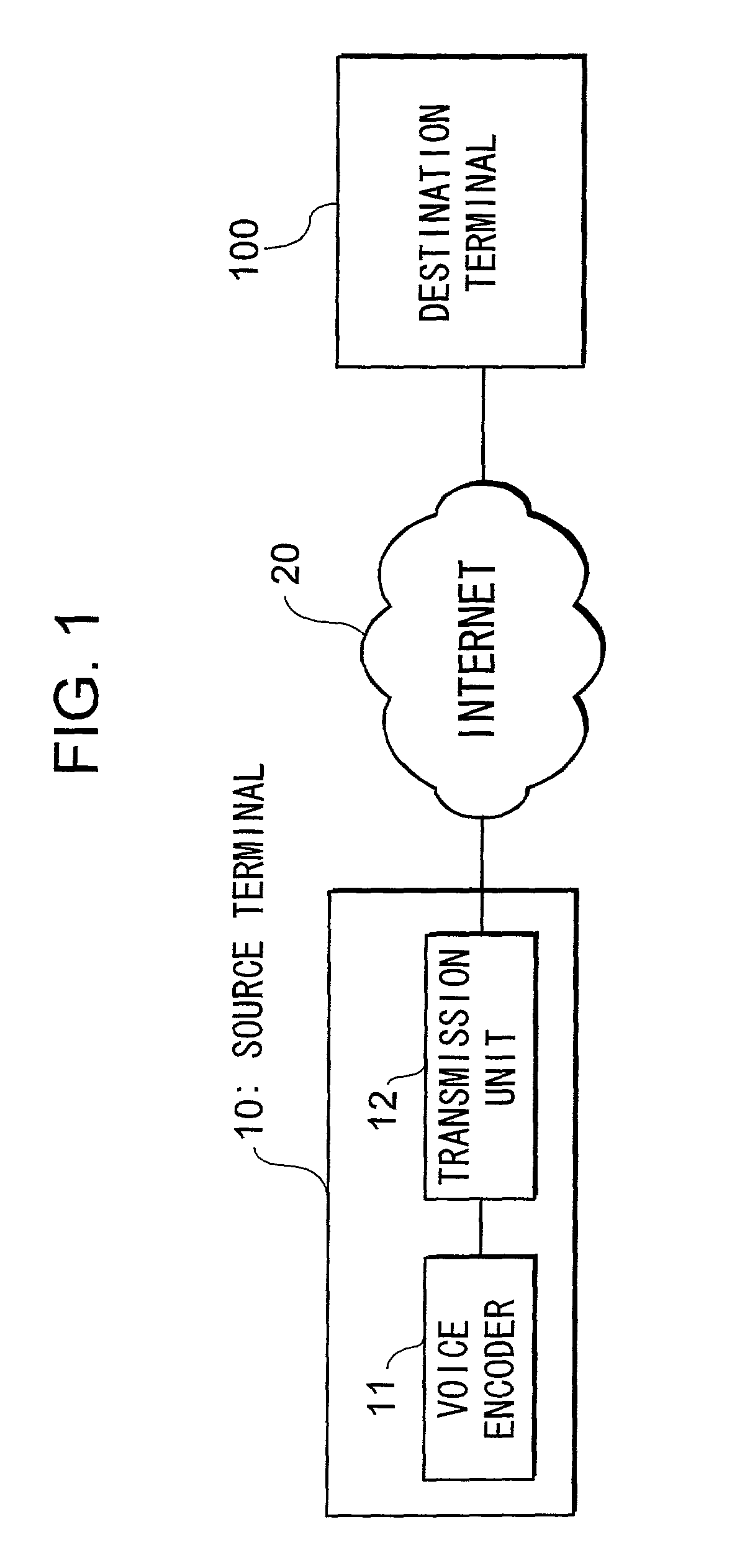
[0053]FIG. 1 is a block diagram showing a configuration of a real-time voice transmission system that is a first embodiment of the present invention. In the real-time voice transmission system, there are provided a source terminal 10 with a voice encoder 11 and a transmission unit 12 as in the conventional art. The source terminal 10 and a destination terminal 100 are both VoIP terminals. This real-time voice transmission system is for providing an Internet telephone service to a user.

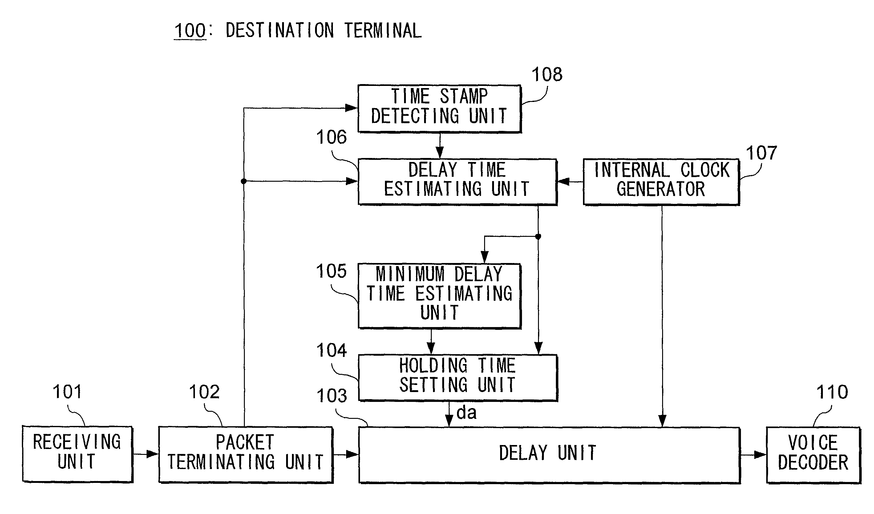
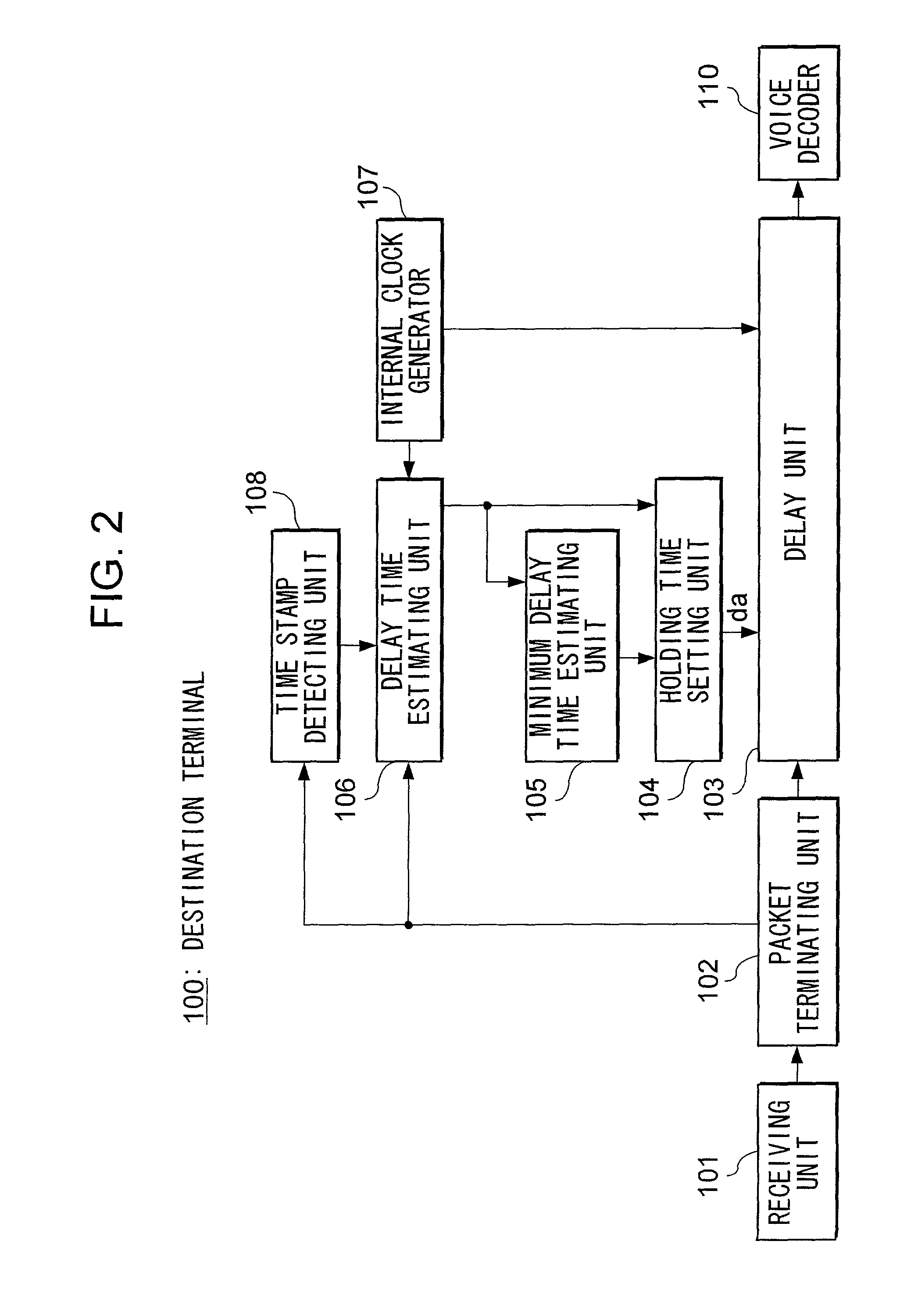
[0054]FIG. 2 is a block diagram showing a configuration of the destination terminal 100. In this figure, a receiving unit 101 is a device which receives voice packets from the source terminal 10 through the Internet 20. A packet terminating unit 102 is a device that terminates a protocol of the Internet 20. A voice packet received by the receiving unit 101 is transmitted through the packet terminating unit 102 to a time stamp detecting unit 108 and a delay time estimating unit 106. A...

second embodiment

B. Second Embodiment

[0079]FIG. 6 is a block diagram showing a configuration of a destination terminal 100 with respect to a second embodiment of the present invention. The destination terminal 100 in this embodiment further contains a non-voice section detecting unit 109 in addition to the components of the destination terminal 100 for the first embodiment. The non-voice section detecting unit 109 monitors the payload of voice packets received in sequence and detects non-voice sections. To describe further in detail, a source terminal 10 in the present embodiment, when a user of the terminal 10 stops vocalization and a non-voice section in which there is no voice to be transmitted begins, transmits to the destination terminal 100 a voice packet which includes information designating the start of the non-voice section in the payload as shown in FIG. 7. The non-voice section detecting unit 109 of the destination terminal 100, by receiving this voice packet, detects the start of a non-...


PUM


Abstract

A delay unit 103 adds holding time that has been set by a holding time setting unit 104 to a received data. The holding time is computed based on delay time of received data and the minimum delay time of data received up to a certain point for the purpose of reducing a total delay time. The delay time is estimated in a delay time estimating unit 106 from the difference between a reception time of a packet counted based on an internal clock generator 107 and a time designated by a time stamp in the received packet.

Description

BACKGROUND OF THE INVENTION[0001]1. Field of Invention[0002]This invention relates to a delay jitter reducing device for sequentially receiving a series of chronological data segments through a transmission path such as the Internet and delaying an individual data segment for an appropriate amount of time, thereby reducing delay jitter that has occurred in the propagation process of an individual data segment and obtaining chronological data segments from which effects of the delay jitter have been eliminated; and a delay jitter reducing method thereof.[0003]2. Description of the Related Art[0004]One form of data transmission is a real-time transmission that transmits a chronological sample of continuous signals such as, for example, voice signals after loading them to a plurality of consecutive packets. In such a real-time transmission, if delay time in transmitting a packet for individual packets are equal to one another, it is possible to obtain a voice signal of the same wavefor...

Claims


Application Information

Patent Timeline
Patent Type & Authority Patents(United States)
IPC IPC(8): H04J3/06H04L12/26H04L12/64H04L47/2416
CPCH04L12/6418H04L29/06027H04L47/10H04L65/80H04L47/28H04L47/2416H04L2012/6472H04L2012/6489H04L65/1101
Inventor SUZUKIKAWAHARA, TOSHIROMORIOKA, MASASHINAKA, NOBUHIKO
Owner NTT DOCOMO INC
Why Eureka
Try Eureka