Ultra wideband (UWB) transmitter architecture

a transmitter and ultra wideband technology, applied in the field of wireless digital communication system system and method, can solve the problems of not being able to generate different pulses, not being able to store a large number of pulses, and simple current source and resistor combination use is not very flexible, so as to reduce the overall cost of the uwb transmitter and save spa

Inactive Publication Date: 2006-01-10
TEXAS INSTR INC
View PDF5 Cites 21 Cited by
  • Summary
  • Abstract
  • Description
  • Claims
  • Application Information

AI Technical Summary

Benefits of technology

[0013]An advantage of a preferred embodiment of the present invention is the pulse generator can be configured to generate a pulse of varying duration, magnitude, and type, to meet changing needs and modulation schemes. The use of a flexible pulse generator allows a single pulse generator to be used in the place of a number of pulse generators, reducing the overall cost of the UWB transmitter.
[0014]A further advantage of a preferred embodiment of the present invention is through the use of a single flexible pulse generator in the place of a number of pulse generators also saves on the amount of space consumed in the implementation of the pulse generator.

Problems solved by technology

One disadvantage of the prior art is that the use of a simple current source and resistor combination is not very flexible.
Therefore, if the need should arise that a different type of pulse is needed, differing in terms of shape, duration, magnitude, etc., then the combination may not be able to generate the different pulse.
A second disadvantage of the prior art is that the use of a memory to store the samples of the pulse to be generated can result in the need to store a large number of different sets of samples to generate different types of pulses at varying durations and magnitudes and polarities.
This can result in the need to have a relatively large memory.
A third disadvantage of the prior art is that the use of stored samples to generate the pulses is the speed of the digital-to-analog converter, which may not be able to perform the conversion at a sufficiently fast rate.

Method used


Image

  • Ultra wideband (UWB) transmitter architecture
  • Ultra wideband (UWB) transmitter architecture
  • Ultra wideband (UWB) transmitter architecture

Examples


Embodiment Construction

[0027]The making and using of the presently preferred embodiments are discussed in detail below. It should be appreciated, however, that the present invention provides many applicable inventive concepts that can be embodied in a wide variety of specific contexts. The specific embodiments discussed are merely illustrative of specific ways to make and use the invention, and do not limit the scope of the invention.

[0028]The present invention will be described with respect to preferred embodiments in a specific context, namely an UWB transmitter. The invention may also be applied, however, to other applications where a flexible pulse generator is needed, such as other types of wired and wireless transmitters, signal generators, any application where a signal of a specifiable duration, magnitude, and type is required, etc.

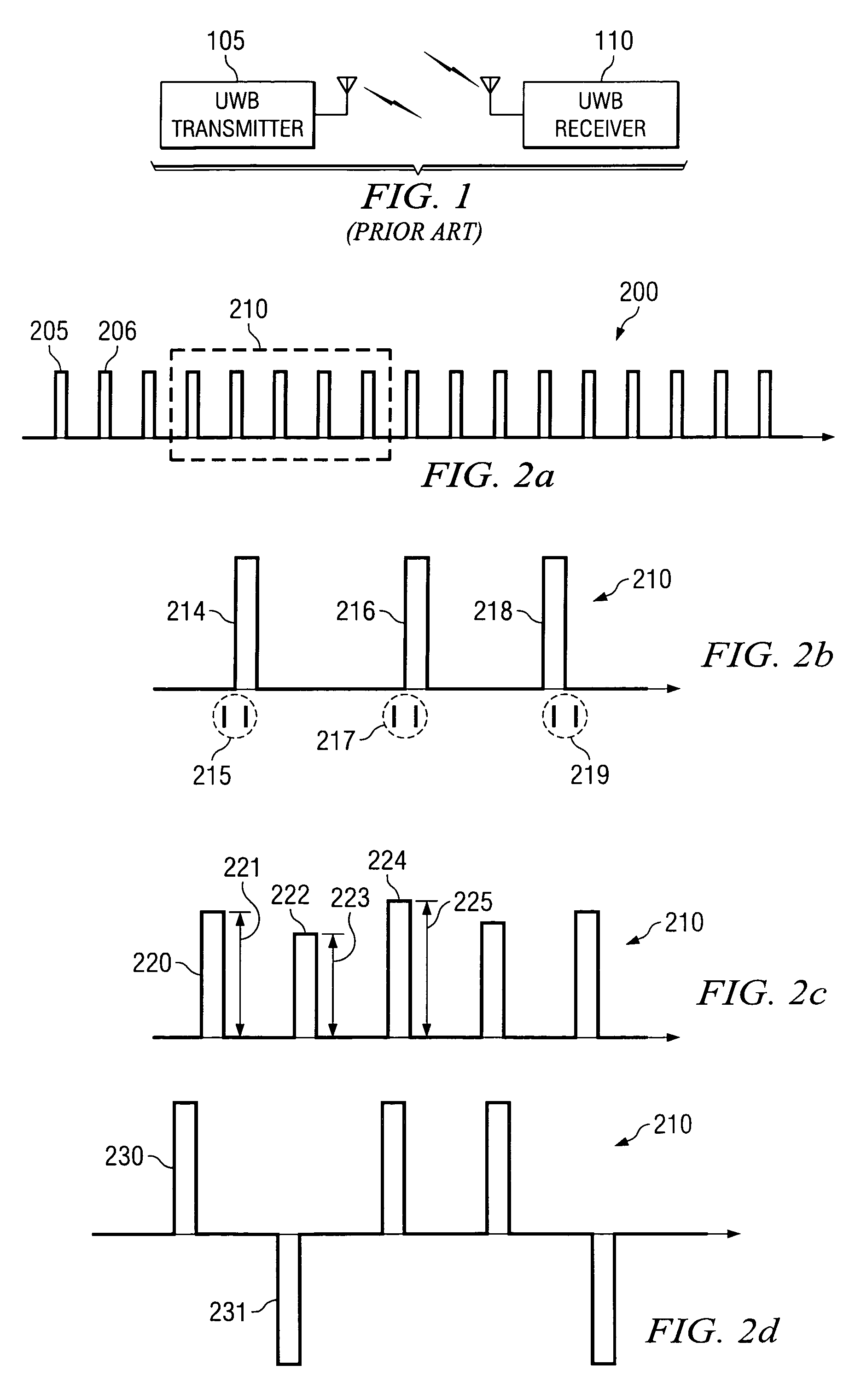
[0029]With reference now to FIG. 1, there is shown an exemplary ultra-wideband (UWB) wireless communications system. The UWB wireless communications system as displayed...


PUM


Abstract

System and method for analog signal generation and manipulation in an ultra-wideband (UWB) transmitter. A preferred embodiment comprises a digital portion 305 of an UWB transmitter (for example, transmitter 300), which is responsible for encoding a data stream to be transmitted, and an analog portion 330. The analog portion 330 creates a stream of short duration pulses from the encoded data stream and then filters the stream of short duration pulses. To simplify the generation of the short duration pulses, a quantized representation of the short duration pulse is used. The quantized representation is created via the use of control signals that by coupling differential amplifiers together (such as amplifier 611), generate a voltage drop across a resistor (such as resistor 619) and hence, a current.

Description

[0001]This application claims the benefit of U.S. Provisional Application No. 60 / 386,821, filed on Jun. 7, 2002, entitled “Ultra-Wideband (UWB) Receiver and Transmitter Architecture,” which application is hereby incorporated herein by reference.TECHNICAL FIELD[0002]The present invention relates generally to a system and method for wireless digital communications systems, and more particularly to a system and method for providing a transmitter for a wireless communications system with a large data bandwidth.BACKGROUND[0003]Ultra-wideband (UWB) communications systems are normally defined as carrier-less communications systems wherein the bandwidth of the signal being transmitted, fB, is greater than or equal to 0.20 fc, where fc is the center frequency of the signal being transmitted. Additionally, the UWB communications system should have a minimum bandwidth of 500 MHz. Note that the definition for UWB communications systems and devices is as defined by the Federal Communications Com...

Claims


Application Information

Patent Timeline
Patent Type & Authority Patents(United States)
IPC IPC(8): H04B14/06H04BH04B1/69H04L27/04
CPCH04B1/7174
Inventor BATRA, ANUJDABAK, ANAND G.GHARPUREY, RANJIT
Owner TEXAS INSTR INC
Why Eureka
Try Eureka