
Delta model processing logic representation and execution system

a processing logic and delta model technology, applied in computing models, multi-programming arrangements, instruments, etc., can solve the problems of difficult programmatically collecting and analysing the processing logic contained in all of the manufacturing and accounting application programs together, and human beings could not easily read the processing logic contained on the plugboards,

Inactive Publication Date: 2006-01-10
CODD EDGAR F +1
View PDF9 Cites 33 Cited by
  • Summary
  • Abstract
  • Description
  • Claims
  • Application Information

AI Technical Summary

Benefits of technology

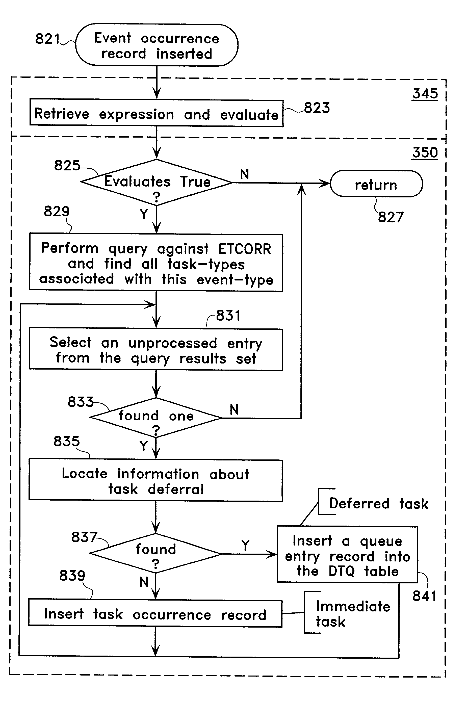
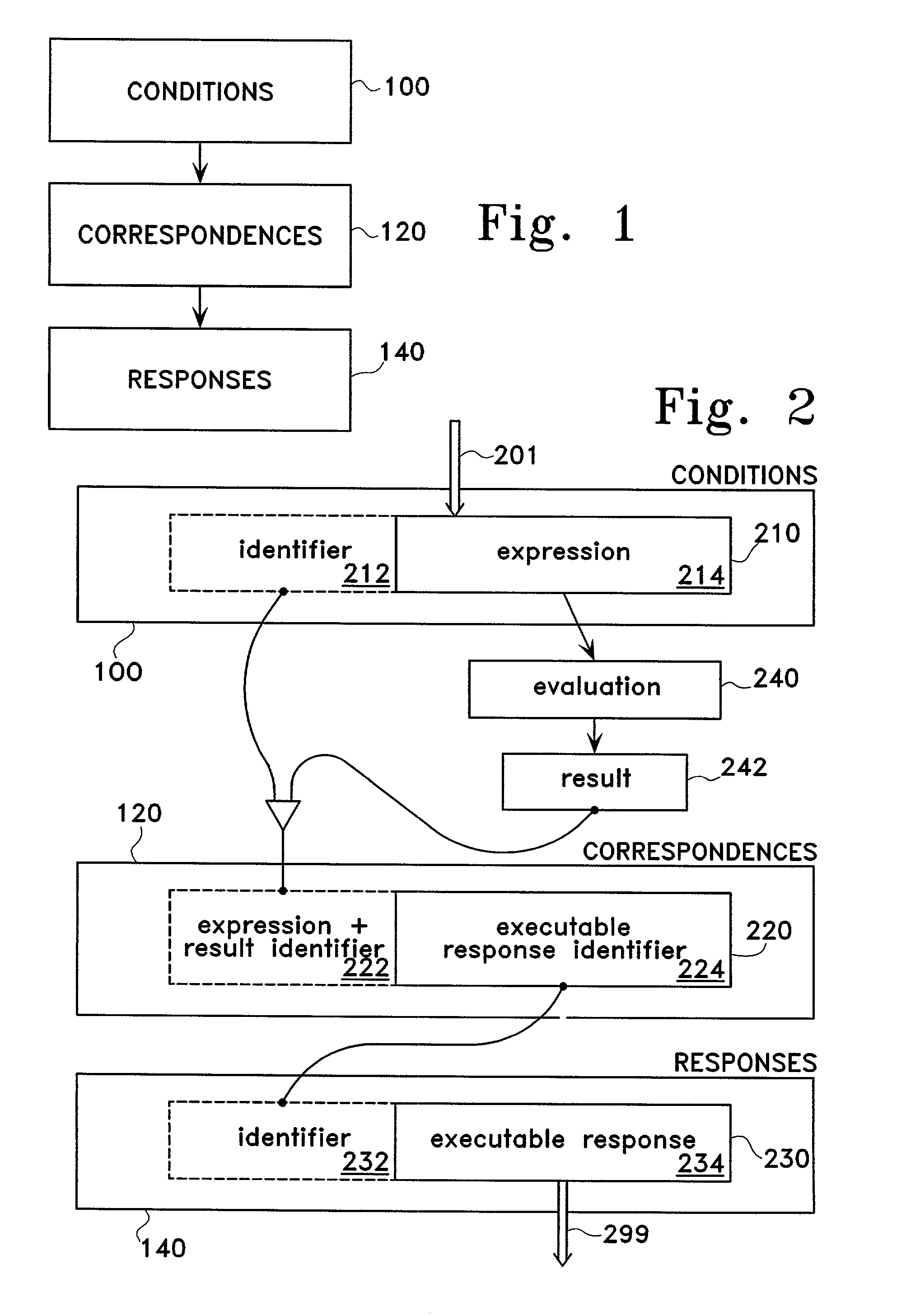
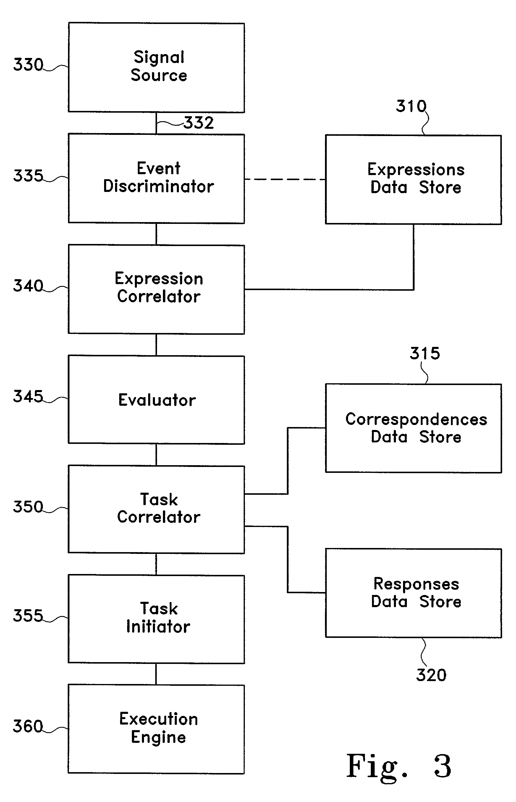
[0018]In other words, the expressions represent conditions placed on the execution of executable responses, the task definitions define a pool of executable responses, and the correspondences relate the conditions to particular executable responses. By separating the expressions from the executable responses, and relating them via the correspondences data structure entries, the processing logic may be easily reconfigured and existing definitions reused.

Problems solved by technology

Humans could not easily read this processing logic contained on the plugboards, and that processing logic represented only a very small and very low-level portion of the rules used to conduct a business enterprise.
Unfortunately, the many possible constructs available for representing these condition-to-action associations obscures their underlying similarity.
The lack of similarity in the representations of the processing logic in traditional programming languages makes it difficult to collect and analyze the processing logic as a whole.
Considering the dissimilar languages employed, the dissimilar ways to represent condition-to-action associations within each language, the dissimilar locations where the application programs may reside, and the dissimilar operating systems and hardware, it would be very difficult to programmatically collect and analyze the processing logic contained in all of the manufacturing and accounting application programs together.
So, in a collective sense, the processing logic of the business cannot be readily collected and analyzed with the aid of the computer, despite the fact that the processing logic embodied in application programs is machine-readable.
The lack of similarity in the representations of the processing logic in conventional programming languages also has disadvantages despite its being human-readable.
At the core of the problem is that fact that the business people responsible for determining the processing logic for the operation of the business enterprise, e.g., supervisors, managers, and directors (managers, or management), generally do not have the technical training required to understand and use computer programming languages.
Besides the inherent delay, this brings with it the possibility that “something gets lost in the translation.” Disconnects frequently result between the business model intended by the management and the business model embodied in the processing logic in the application programs.
Again, because of the diversity of programming languages, a generalized tool would be difficult to develop and any such tool would likely be restricted as a practical matter to particular programming languages, hardware, and operating systems.
First, this may not be practical because of a need to use multiple computing platforms, some of which may be incapable of supporting the standard language.
Further, the business enterprise may purchase some of its applications from software vendors and have no control over the language in which it is written.
. . CASE; and managers are unlikely to have or obtain the technical training required to understand and use the language.

Method used


Image

  • Delta model processing logic representation and execution system
  • Delta model processing logic representation and execution system
  • Delta model processing logic representation and execution system

Examples


Embodiment Construction

[0034]The present invention comprises novel method, apparatus, and data structures for representing and executing processing logic. The following description is presented to enable any person skilled in the art to make and use the invention, and is provided in the context of particular applications and their requirements. Various modifications to the preferred embodiment will be readily apparent to those skilled in the art, and the generic principles defined herein may be applied to other embodiments and applications without departing from the spirit and scope of the invention. Thus, the present invention is not intended to be limited to the embodiment shown, but is to be accorded the widest scope consistent with the principles and features disclosed herein.

PMKBS Structural Overview

[0035]FIG. 1 depicts a block diagram of data stores for processing logic elements encoded in a memory medium in one embodiment. Processing logic elements comprise individual memory-encoded representation ...


PUM


Abstract

The invention presents novel method, apparatus, and data structures for storing, maintaining, and executing processing logic on a computer system. Processing logic is encoded into its distinct, constituent elements that are flexibly linked, facilitating reuse and reconfiguration. Executable responses are selected for an input signal by identifying a correspondence between the input signal and an expression, evaluating the expression to a resulting value, and identifying a correspondence between the expression and its resulting value, and an executable response.

Description

CROSS-REFERENCE TO RELATED APPLICATIONS[0001]This application is a continuation application of U.S. application Ser. No. 08 / 872,531, filed Jun. 11, 1997 now U.S. Pat. No. 6,421,667, which claims the benefit of U.S. Provisional Application No. 60 / 019,572, filed Jun. 11, 1996 and U.S. Provisional Application No. 60 / 030,349, filed Nov. 6, 1996 and U.S. Provisional Application No. 60 / 033,008, filed Dec. 16, 1996 and U.S. Provisional Application No. 60 / 034,206 filed Jan. 21, 1997 and U.S. Provisional Application No. 60 / 036,702 filed Jan. 31, 1997.FIELD OF INVENTION[0002]The invention relates generally to computer-based process execution systems, and more particularly, to the optimized representation of processing logic.DESCRIPTION OF THE RELATED ART[0003]In the earliest days of electronic data processing, jumper wires on plugboards contained the definition of the process a machine was supposed to execute. Humans could not easily read this processing logic contained on the plugboards, and...

Claims


Application Information

Patent Timeline
IPC IPC(8): G06F17/00G06F9/44
CPCG06F9/44Y10S707/99943Y10S707/99934Y10S707/99935Y10S707/99936
Inventor CODD, EDGAR F.CODD, SHARON B.
Owner CODD EDGAR F
Learn More