Piloted airblast lean direct fuel injector with modified air splitter

Active Publication Date: 2006-01-17
ROLLS ROYCE PLC
View PDF15 Cites 50 Cited by
  • Summary
  • Abstract
  • Description
  • Claims
  • Application Information

AI Technical Summary

Benefits of technology

[0008]This invention provides fuel injector systems that enable improved combustion efficiencies a

Problems solved by technology

Advanced gas turbine combustors must meet these requirements for lower NOx emissions under conditions in which the control of NOx generation is very challenging.
The severe combustor pressure and temperature conditions required for improved fuel efficiency make the NOx emissions goal much more difficult to achieve.
If the mixing occurs very rapidly, the opportunity for near stoichiometric burning is limited, resulting in low NOx production.
Conventional fu

Method used


Image

  • Piloted airblast lean direct fuel injector with modified air splitter
  • Piloted airblast lean direct fuel injector with modified air splitter
  • Piloted airblast lean direct fuel injector with modified air splitter

Examples


Embodiment Construction

[0019]One of the mechanisms forcing the combustion instability is the modulation of equivalence ratio at the flamefront, caused by a modulation of the inner airstream as the combustor pressure fluctuates. This determination is based on numerical predictions in which the predicted instability is dampened when the airflow in the inner main airstream is held constant at the swirl vane exit.

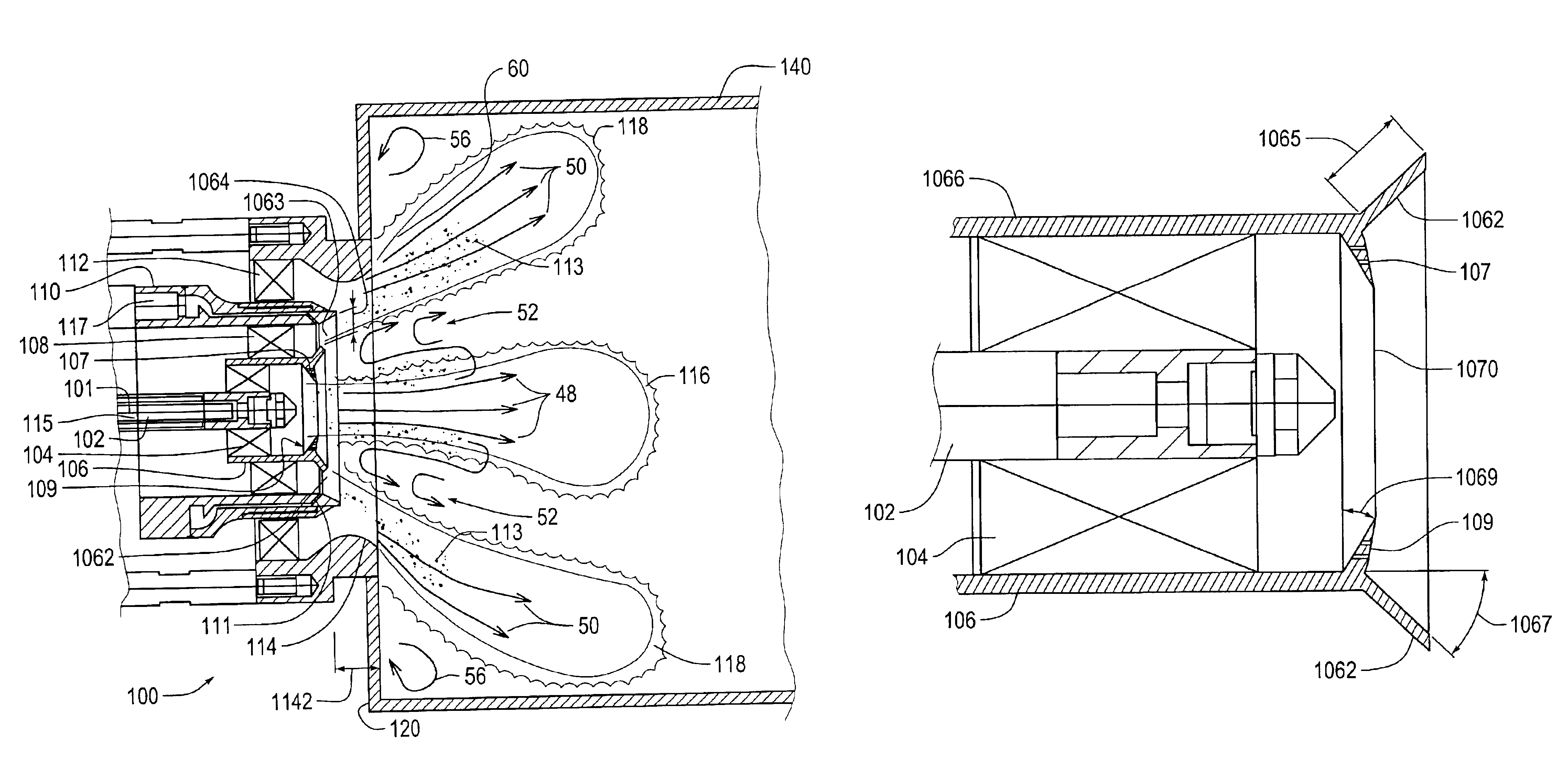
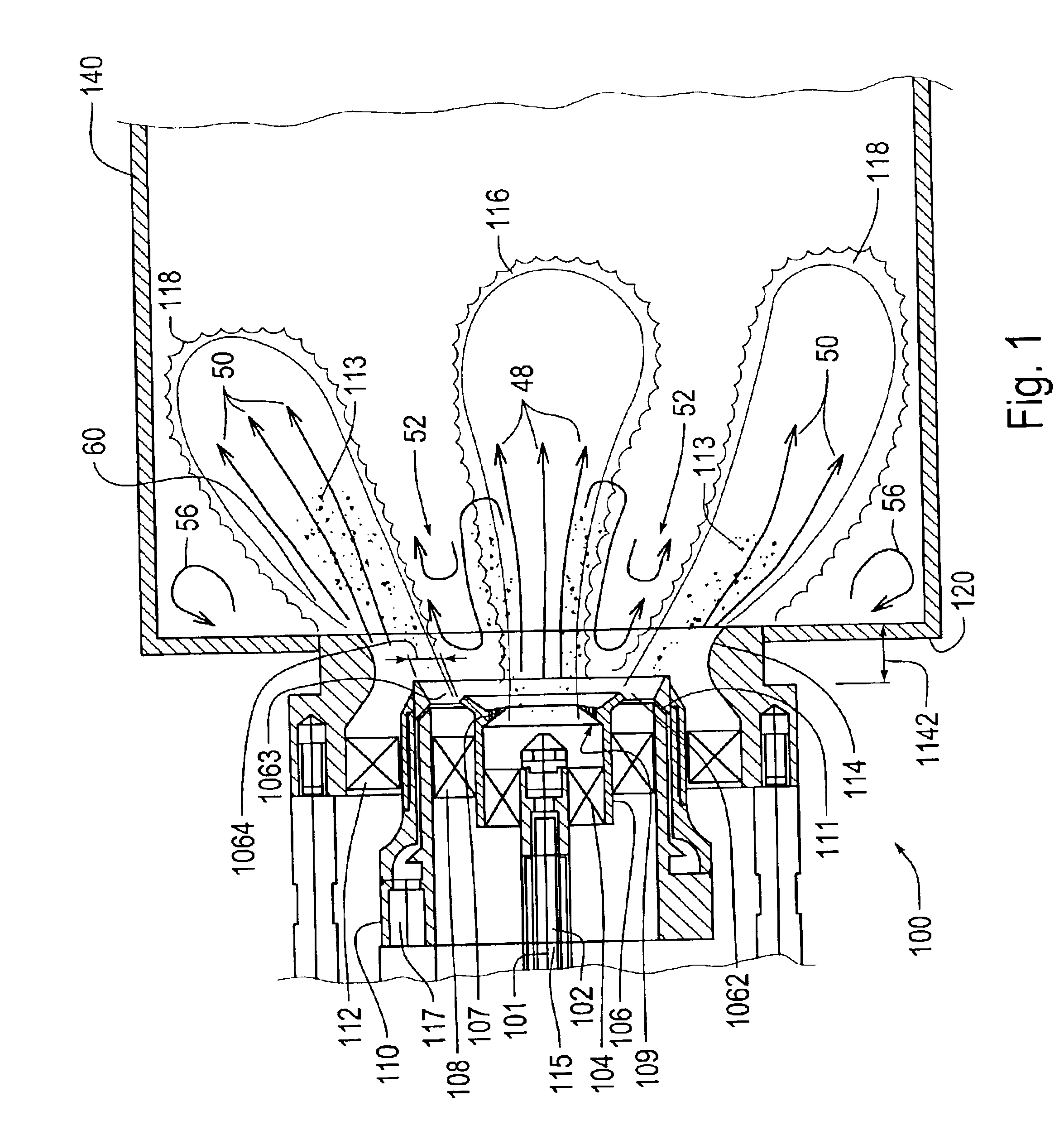
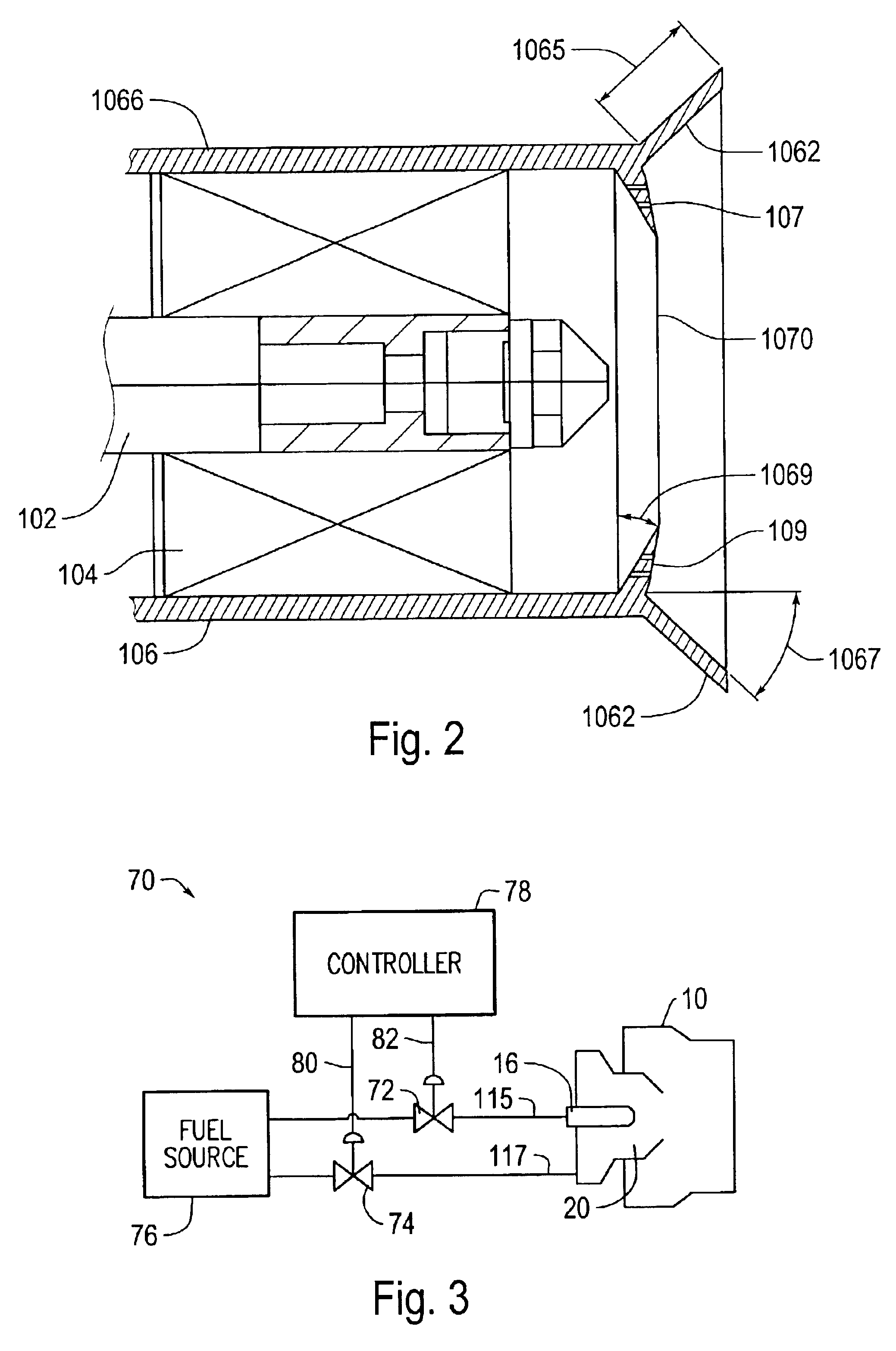
[0020]FIG. 1 shows a cross-sectional schematic view of one exemplary embodiment of a piloted airblast fuel injector system 100 with a modified air splitter according to this invention. FIG. 2 shows in more detail the modified air splitter region of the piloted airblast fuel injector system of FIG. 1. The piloted airblast fuel injector system 100 includes three air passages and two fuel injectors. The piloted airblast fuel injector system 100 is mounted upon the dome wall 120 of a combustor 140 of a gas turbine engine.

[0021]As shown in FIGS. 1 and 2, in one exemplary embodiment, the piloted airblast f...


PUM


Abstract

A fuel injector system that reduces and/or eliminates combustion instability. The fuel injector system includes a pilot fuel injector, a pilot swirler that swirls air past the pilot fuel injector, a main airblast fuel injector having an aft end, inner and outer main swirlers that swirl air past the main airblast fuel injector, and an air splitter located between the pilot swirler and the inner main swirler. The air splitter includes at least one aft end cone angled radially outboard and axially positioned downstream of the main airblast fuel injector aft end. The air splitter divides a pilot air stream exiting the pilot swirler from an inner main air stream exiting the inner main swirler to create a bifurcated recirculation zone.

Description

BACKGROUND OF THE INVENTION[0001]1. Field of Invention[0002]The present invention relates generally to fuel injection assemblies for gas turbine engines.[0003]2. Description of Related Art[0004]There is a continuing need, driven by environmental concerns and governmental regulations, for improving the efficiency of and decreasing the emissions from gas turbine engines of the type utilized to power jet aircraft or generate electricity. Particularly, there is a continuing drive to reduce nitrous oxide (NOx) emissions.[0005]Advanced gas turbine combustors must meet these requirements for lower NOx emissions under conditions in which the control of NOx generation is very challenging. For example, the goal for the Ultra Efficient Engine Technology (UEET) gas turbine combustor research being done by NASA is a 70 percent reduction in NOx emissions and a 15 percent improvement in fuel efficiency compared to ICAO 1996 STANDARDS TECHNOLOGY. Realization of the fuel efficiency objective will re...

Claims


Application Information

Patent Timeline
IPC IPC(8): F02C7/22F02C7/26F23R3/14F23R3/18F23R3/34
CPCF23R3/343F23R3/18F23R3/14F23D2900/00015F23D2900/00018
Inventor SMITH, CLIFFORD E.NICKOLAUS, DANIEL A.
Owner ROLLS ROYCE PLC
Why Eureka
Try Eureka