Electronically controlled throttle control apparatus

a throttle control and electric control technology, applied in the direction of electric control, combustion air/fuel air treatment, machines/engines, etc., to achieve the effect of reducing the rotational load, and reducing the sliding resistance during the relative movement between the rotator and the coil spring

Active Publication Date: 2006-01-17
DENSO CORP
View PDF7 Cites 14 Cited by
  • Summary
  • Abstract
  • Description
  • Claims
  • Application Information

AI Technical Summary

Benefits of technology

[0013]Therefore, an object of the present invention is to provide an electronically controlled throttle control apparatus which can remove abrasive dust occurring from a member for making sliding contact with the coil spring or abrasive dust occurring from the coil spring itself because of sliding contact with the member, i.e., abrasive dust resulting from sliding friction between the coil spring and the member in sliding contact with this coil spring at least from a sliding contact portion between the power transmission device and the coil spring, thereby preventing the throttle valve from malfunctioning due to a deterioration in sliding resistance ascribable to the intervention of the abrasive dust in the sliding contact portion between the power transmission device and the coil spring. Another object is to provide an electronically controlled throttle control apparatus which can avoid malfunction of the power transmission device for transmitting the rotational power of the actuator to the throttle valve and the throttle shaft.

Problems solved by technology

Consequently, it becomes difficult for the abrasive dust occurring from the member for making sliding contact with the coil spring or the abrasive dust occurring from the coil spring itself because of sliding contact with the member to lie at least in the sliding contact portion between the power transmission device and the coil spring, so that the foregoing abrasive dust becomes less likely to be rubbed against the surface of the power transmission device or the surface of the coil spring at the time of sliding friction due to relative movement between the power transmission device and the coil spring.

Method used


Image

  • Electronically controlled throttle control apparatus
  • Electronically controlled throttle control apparatus
  • Electronically controlled throttle control apparatus

Examples


modified examples

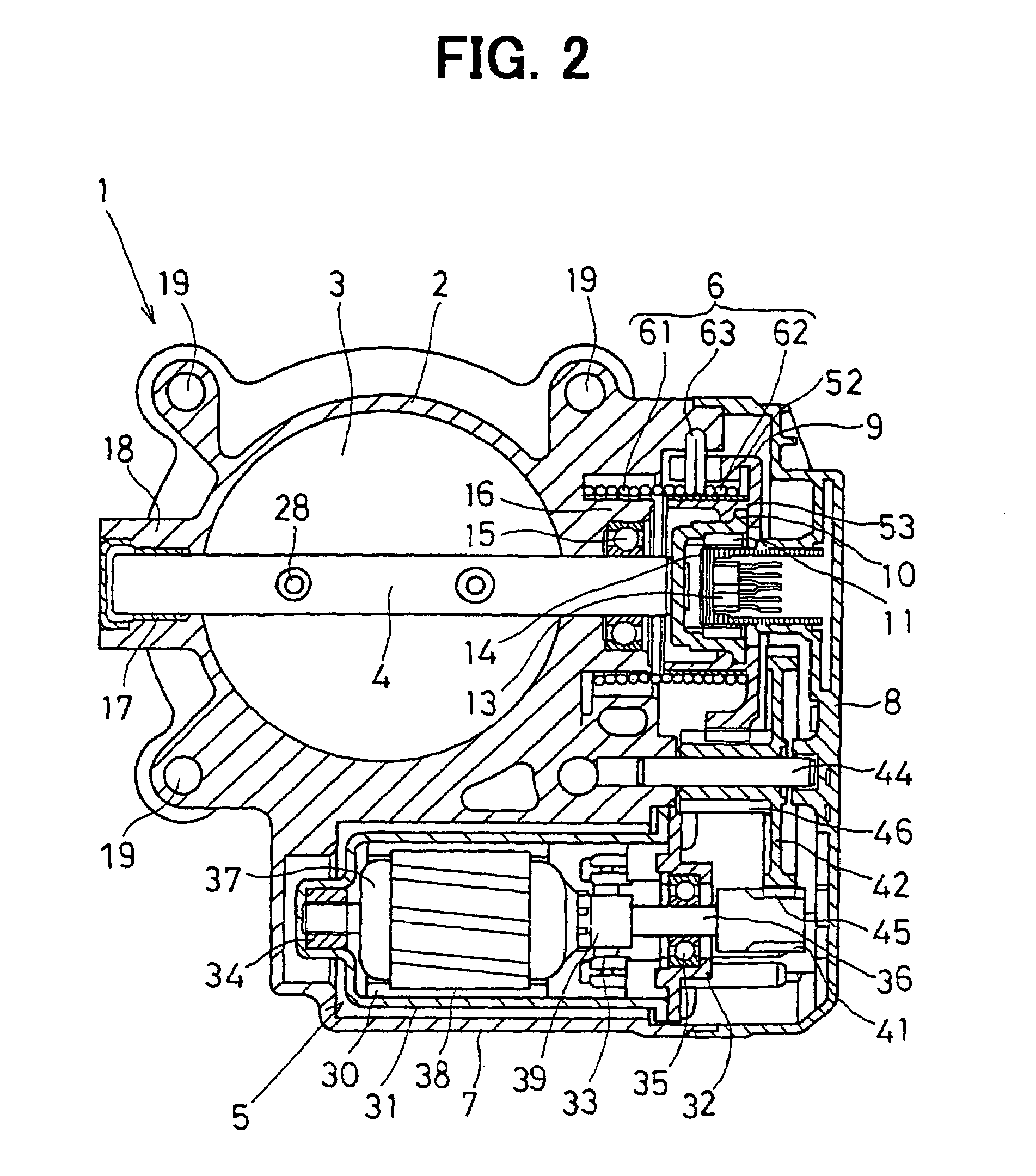
[0168]While the present embodiments have dealt with the case where the Hall device 13 is used as the detecting device of a noncontact type, a Hall IC, a magneto-resistive device, or the like may be used as the detecting device of noncontact type. Moreover, while the present embodiments have dealt with the case where the permanent magnets 11 of split type are used as the magnetic field generating source, a permanent magnet of cylindrical shape may be used as the magnetic field generating source.

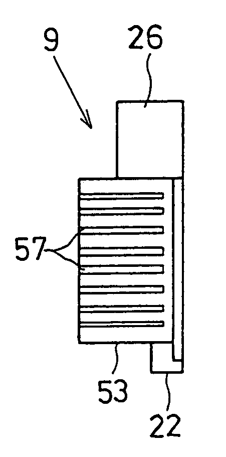
[0169]Incidentally, the single coil spring 6, i.e., the return spring (first spring part) 61 or the default spring (second spring part) 62, or the default spring (second spring part) 62 in particular, may be a regular pitch coil having a coil outside diameter generally constant in the direction of the center axis and a constant coil pitch, a variable pitch coil having a coil outside diameter generally constant in the direction of the center axis and varying coil pitches, or a nonlinear spring ...


PUM


Abstract

An electronically controlled throttle control apparatus prevents a throttle valve from malfunctioning due to deterioration in sliding resistance ascribable to abrasive dust at a sliding contact portion between a valve gear of a geared reduction device and a coil spring. The outer periphery of a spring inner periphery guide is provided with a plurality of groove portions as abrasive dust removing means for removing abrasive dust at least from a sliding contact portion between the outer periphery of the spring inner periphery guide and the inner periphery of a default spring, so that individual edge portions of the plurality of groove portions can rub the inner periphery of the default spring to scrape off abrasive dust from the inner periphery of the default spring and direct the abrasive dust into the plurality of groove portions.

Description

CROSS REFERENCE TO RELATED APPLICATIONS[0001]This application is a divisional of our copending commonly assigned application 10 / 793,053 filed Mar. 5, 2004 (now allowed).[0002]This application is based upon, claims the benefit of priority of, and incorporates by reference Japanese Patent Application No. 2003-61305 filed Mar. 7, 2003, No. 2003-74432 filed Mar. 18, 2003, and No. 2003-426955 filed Dec. 24, 2003.FIELD OF THE INVENTION[0003]The present invention relates to an electronically controlled throttle control apparatus for controlling the amount of intake air into an internal combustion engine by adjusting the valve opening of a throttle valve through the operation of a drive motor.BACKGROUND OF THE INVENTION[0004]Conventionally, there have been proposed electronically controlled throttle control apparatuses which have an opener side function of mechanically holding a throttle valve in a predetermined intermediate position between a fully-closed position and a fully-open position...

Claims


Application Information

Patent Timeline
Patent Type & Authority Patents(United States)
IPC IPC(8): F02M35/00F02D9/02F02D9/10F02D11/10
CPCF02D9/1065F02D11/10F02D11/107F16K31/563F16F1/12F16K1/221F02D2009/0294F02D2009/0267
Inventor TANIMURA, HIROSHIUEHAMA, MOTOKIKAMIYA, AKIHIROARAI, MASATO
Owner DENSO CORP
Why Eureka
Try Eureka