Hydraulic shock absorber

Active Publication Date: 2006-01-17
THYSSENKRUPP BILSTEIN
View PDF7 Cites 9 Cited by
  • Summary
  • Abstract
  • Description
  • Claims
  • Application Information

AI Technical Summary

Benefits of technology

[0006]The object of the present invention is accordingly an improved bypass that, while simple in structure, will be less subject to the aforesaid drawback.
[0007]The dashpot in accordance with the present invention has several advantages that derive from the bypass being controlled by a component of much lighter mass. In one version caps are maintained axially separated by a spring, the bypass-control component will not need to be constantly accelerated

Problems solved by technology

There is a drawback to this system.
Since the direction traveled by the control rod constantly changes in accordance with the direction traveled by the dashpot, and since the flanges are constantly hitting t

Method used


Image

  • Hydraulic shock absorber
  • Hydraulic shock absorber
  • Hydraulic shock absorber

Examples


Embodiment Construction

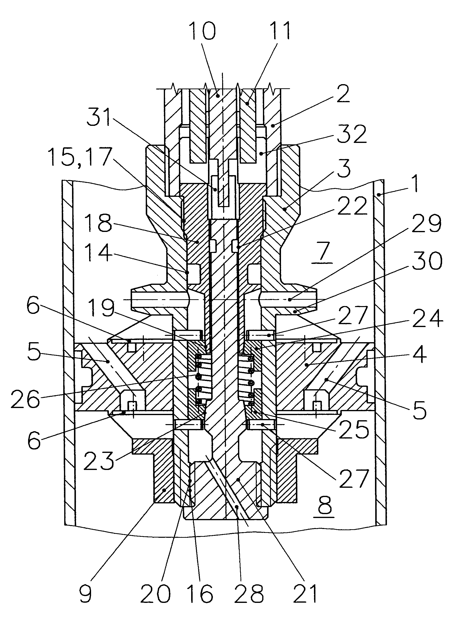
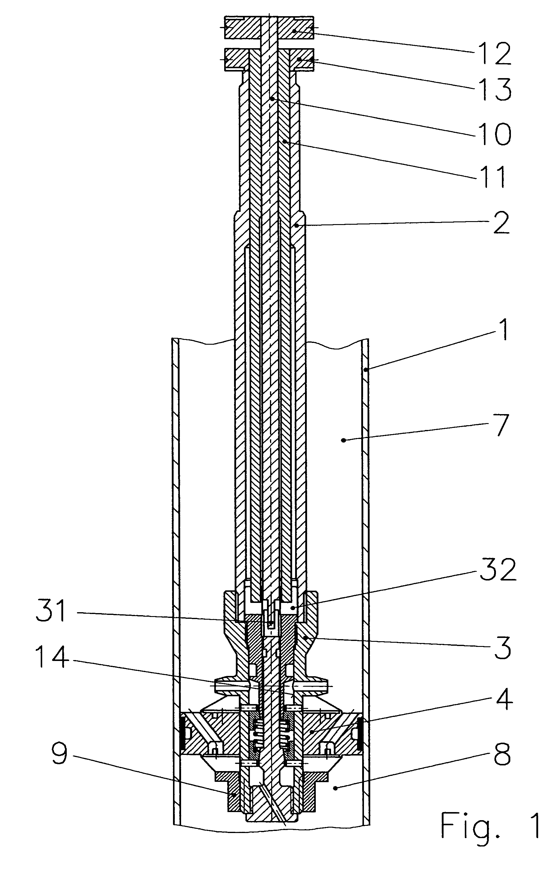
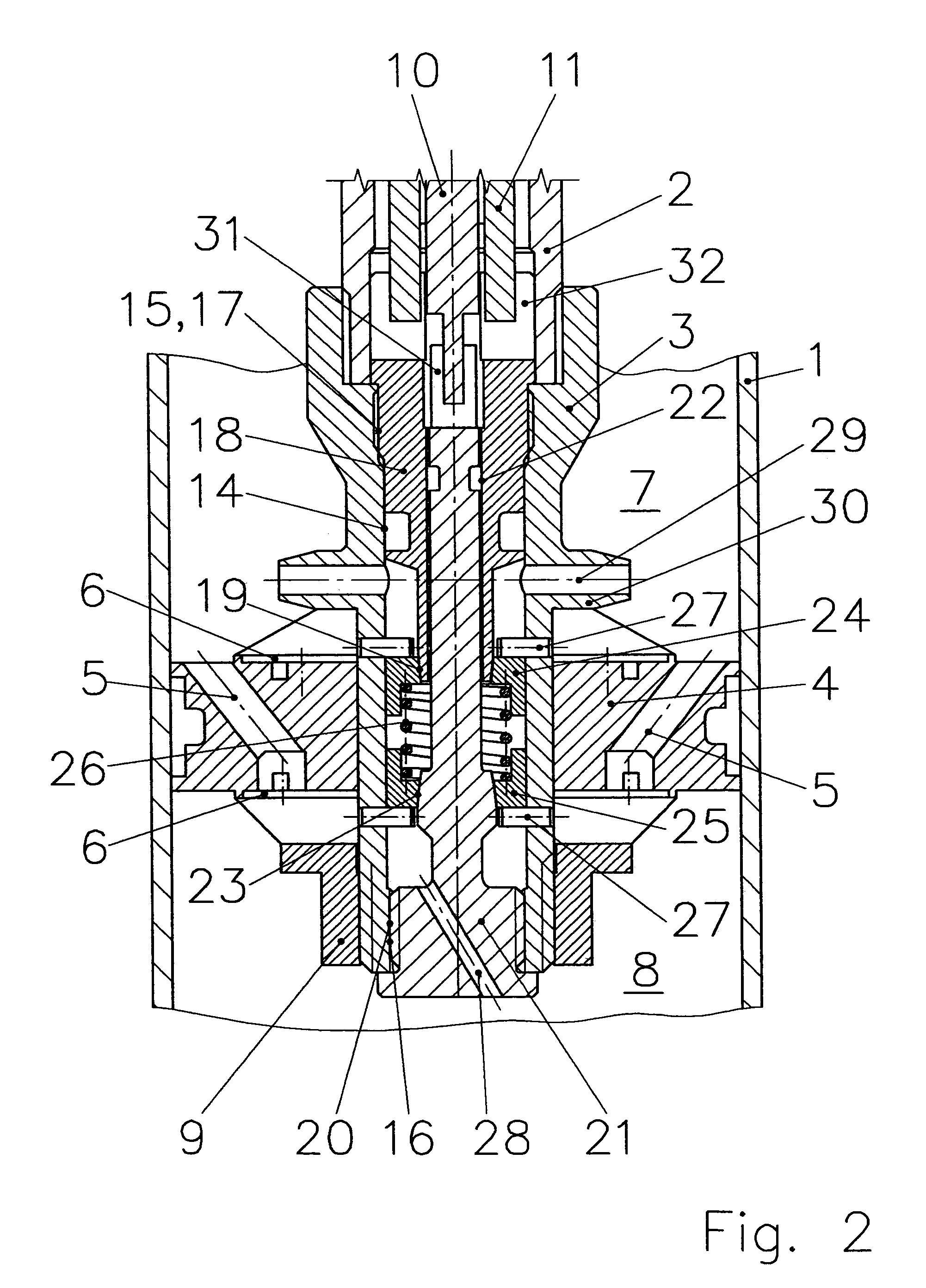
[0012]With piston rod 2 in the suction phase, the fluid flows out of upper compartment 7 and into lower compartment 8 through piston 4. In this phase, the fluid is decelerated by breaches 5 and by the valves. In the compression phase, the fluid flows through piston 4 in the opposite direction, out of lower compartment 8 and into upper compartment 7.

[0013]Piston 4 is fastened to extension 3 by fasteners, e.g. nut 9.

[0014]To facilitate installing the bypass, piston rod 2 is provided with an axial bore, extending in the illustrated example through the center. Extension 3 is also provided with such a bore. The adjustable bypass itself is accommodated in the extension, the bore through the center of piston rod 2 accommodating associated controls, specifically a bypass-control rod 10 and, enclosing it, a bypass-control tube 11. Outside piston rod 2, bypass-control rod 10 and bypass-control tube 11 are provided with bypass-adjustment wheels 12 and 13. The open cross-section of the bypass c...


PUM


Abstract

A hydraulic dashpot with a cylinder (1), a piston (4), and a bypass. The cylinder is charged with fluid. The piston partitions the cylinder into two compartments (7&8), travels back and forth therein on the end of a piston rod (2), and is provided with breaches and valves. The open cross-section of the bypass can be expanded and contracted and fixed in accordance with the direction the piston is traveling in, depending on whether the dashpot is in the compression or in the suction phase. The bypass is provided with an axially displaceable control component. One end of the control component comes to rest against a valve, its displacement being limited by stops. The bypass is accommodated in an axial bore through the piston rod. The bypass operates in conjunction with various outlets that open into the compartments. The control component is provided with at least one lateral flange and travels back and forth in at least one tube. The object is a smooth performance curve and low wear. The control component is accordingly in several parts, comprising at least two bypass control caps that axially travel up to stationary stops. The caps, in conjunction with axially variable components (18&21) that dictate the size of the open cross-section in both the compression and the suction phase, create a port.

Description

BACKGROUND OF THE INVENTION[0001]Hydraulic dashpots are employed to absorb the shock that accompanies the motion of spring-articulated wheel suspensions, preferably in motor vehicles.[0002]The shock is absorbed by forcing fluid out of one compartment and into another in a cylinder through preferably spring-loaded ports in a piston.[0003]A known method of ensuring well defined shock absorption at low piston speeds is to provide bypasses hydraulically paralleling the ports, the two compartments communicating through the bypasses. Providing the bypasses with variable open cross-sections is also known.[0004]German 10 138 487 C1 discloses a dashpot of this genus. It includes a bypass accommodated in a bore through the center of the piston rod. The bypass operates in conjunction with lateral outlets leading out of the piston rod. The bypass is adjusted to the various motions of a dashpot piston in the device's cylinder (1) (compression phase and suction phase), by a control rod fitted wit...

Claims


Application Information

Patent Timeline
IPC IPC(8): F16F9/56F16F9/46F16F9/516
CPCF16F9/516F16F9/467
Inventor HONIG, MICHAELPOETSCH, GUNTERKLOSS, HENDRIKMAGES, STEFAN
Owner THYSSENKRUPP BILSTEIN
Why Eureka
Try Eureka