
Transfer system

a technology of transfer lines and parts, applied in the field of transfer systems, can solve the problems of difficult to secure a space for smoothly supplying parts to these transfer lines, and achieve the effect of smooth supply and discharg

Inactive Publication Date: 2006-01-17
HONDA MOTOR CO LTD
View PDF19 Cites 4 Cited by
  • Summary
  • Abstract
  • Description
  • Claims
  • Application Information

AI Technical Summary

Benefits of technology

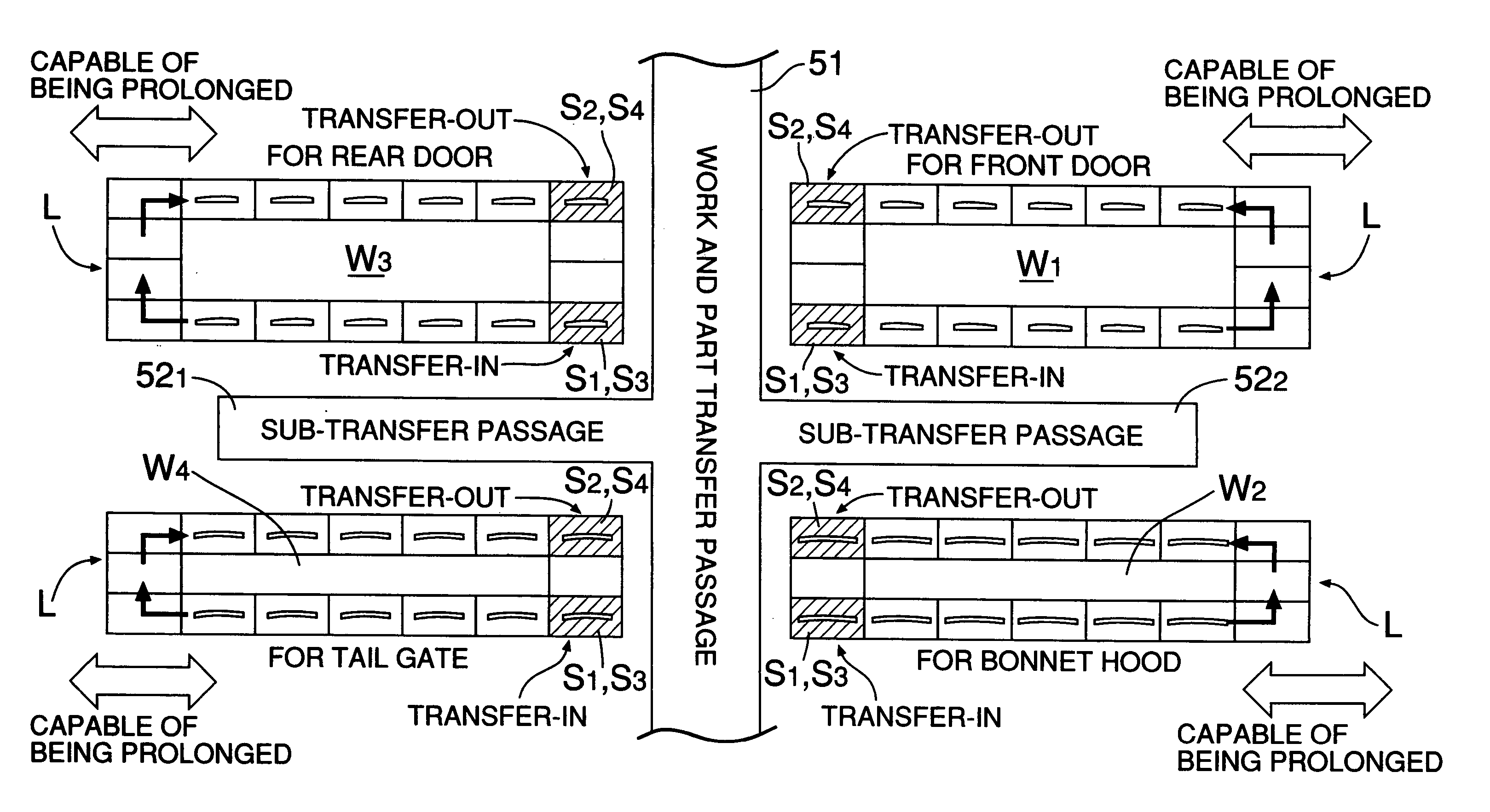
[0007]With the above arrangement, the longitudinal ends of each of the plural transfer lines face a side of the work and part transfer passage, and the transfer-in stations and the transfer-out stations are disposed at each of the longitudinal ends of each of the transfer lines. Therefore, the plurality of the transfer lines can be compactly disposed in a required minimum space while facilitating smooth supply and discharge of the works and parts, from the common work and part transfer passage, with respect to the plurality of the transfer lines. Further, the sub-transfer-passages branching out from the work and part transfer passage are disposed on longitudinally sides of the transfer lines. Therefore, it is possible to easily supply the parts to the intermediate portions of the transfer lines.
[0009]With the above arrangement, since the longitudinal ends of the pair of the transfer lines face opposite sides of the work and part transfer passage, it is possible to effectively utilize a narrow long space to compactly dispose therein the pair of the transfer lines.
[0011]With the above arrangement, the transfer directions of the pair of the transfer lines disposed on the opposite sides of the work and part transfer passage are reverse to each other, the transfer-in stations of one transfer line oppose to the same of the other transfer line, with the work and part transfer passage therebetween; and the transfer-out stations of one transfer line oppose to the same of the other transfer line, with the work and part transfer passage therebetween. Therefore, it is possible to further smoothly perform the supply and discharge between the work and part transfer passage and the transfer lines.
[0013]With the above arrangement, since the pair of the transfer lines are disposed along one side of the sub-transfer-passages, and another pair of the transfer lines are disposed along the other side of the sub-transfer-passages, it is possible to smoothly perform the supply and discharge between the work and part transfer passage and the total four transfer lines while compactly disposing the four transfer lines.

Problems solved by technology

However, since it is necessary to supply parts to be assembled to a work from the outside, to the carriage in succession, the above known system suffers from a problem that, when a plurality of transfer lines are additionally provided in the system, it is difficult to secure a space for smoothly supplying the parts to these transfer lines and to enhance the working efficiency.

Method used


Image

  • Transfer system
  • Transfer system
  • Transfer system

Examples


Embodiment Construction

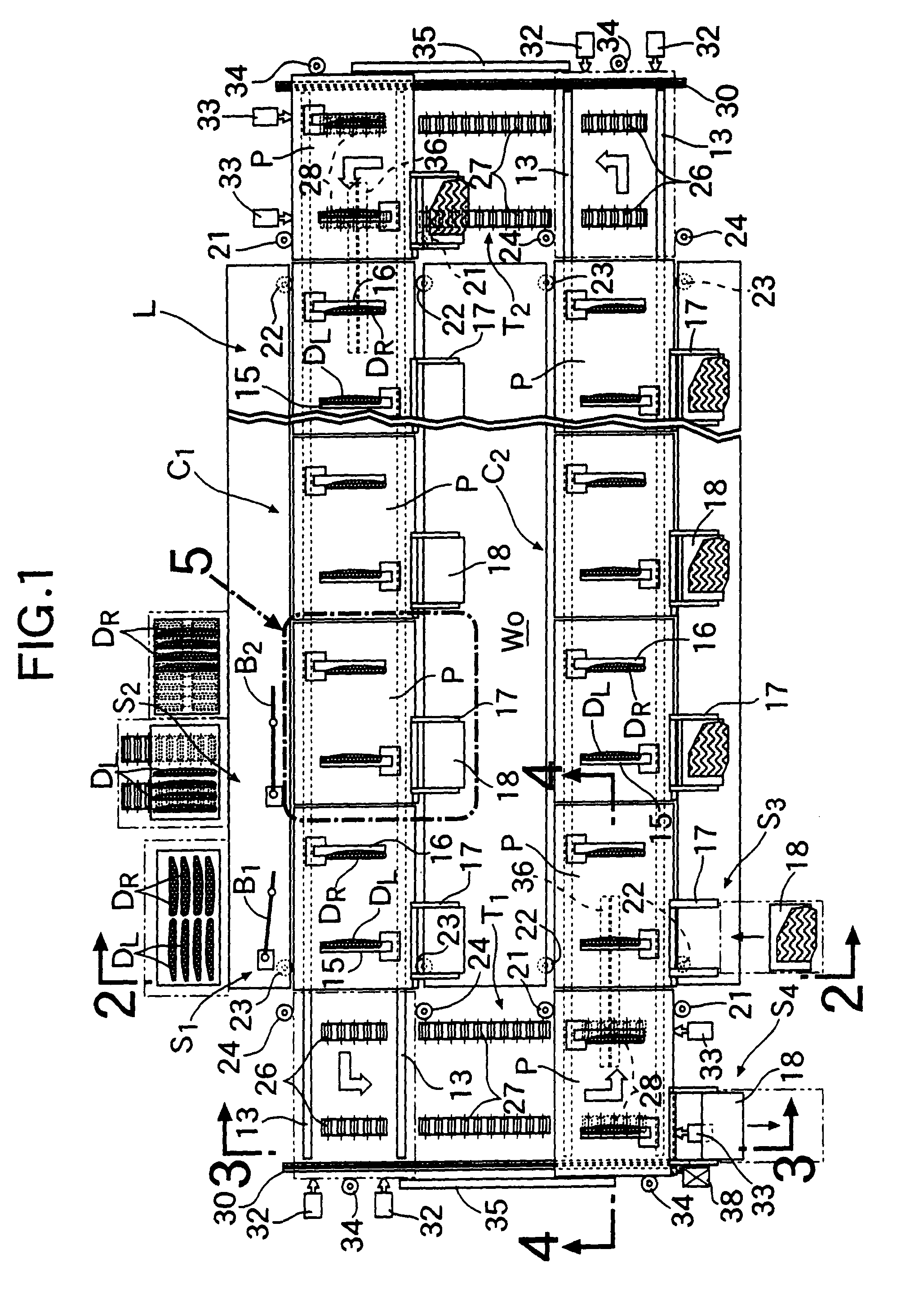
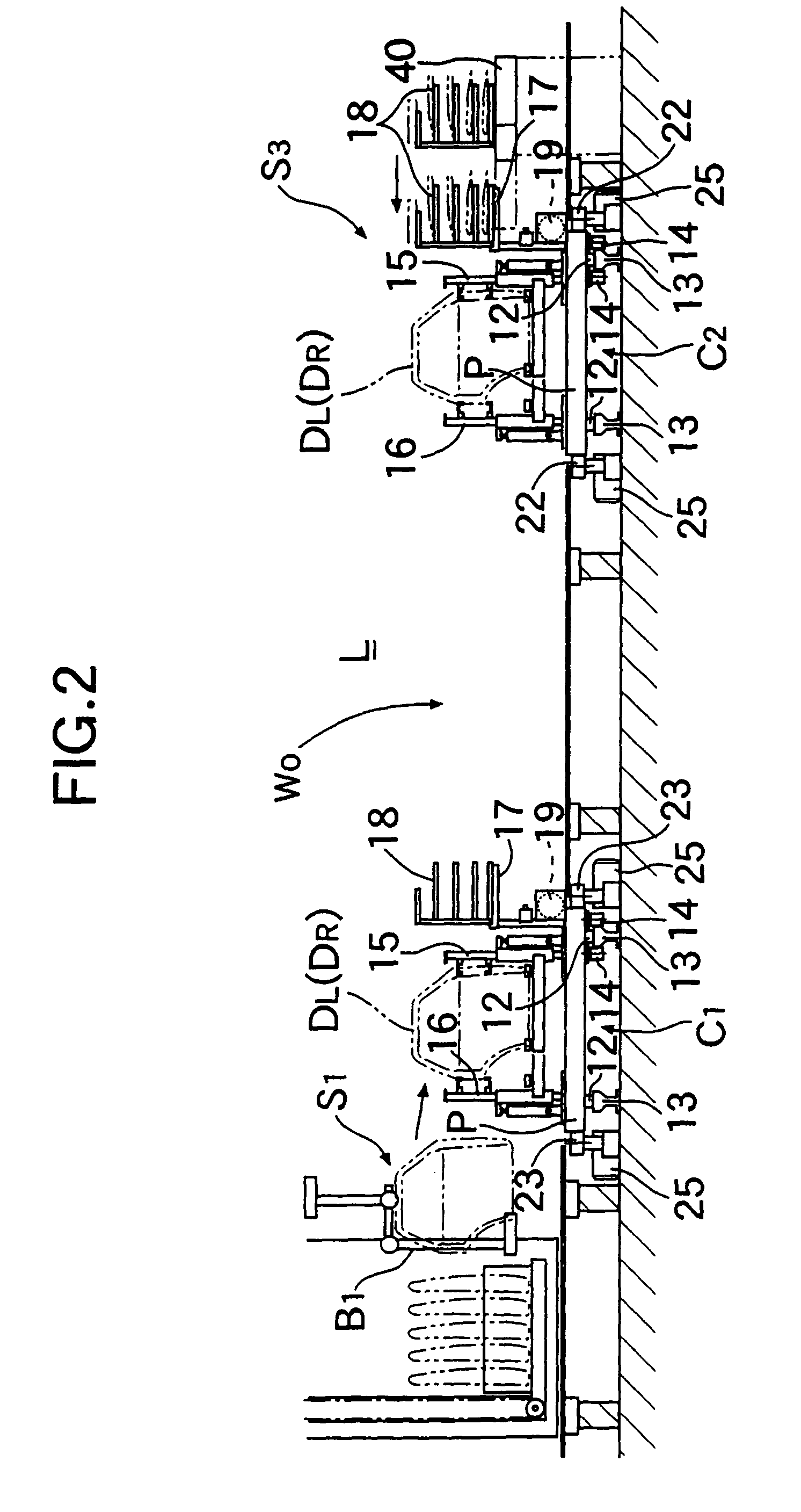
[0015]As shown in FIG. 1, a transfer system of this embodiment is utilized in a sub-line provided sideways of a main line for assembling an automobile, and is operable to assemble parts by an operator riding on a pallet P, while circulating left and right rear doors DL and DR as works removed from a vehicle body of an automobile flowing in a main line on a closed transfer line L in a state in which they have been placed on the pallet P. The left and right rear doors DL and DR having the parts assembled thereto are returned to the main line where they are attached again to the vehicle body of the automobile.

[0016]The transfer line L in the transfer system is comprised of a first conveyer C1 and a second conveyer C2 disposed in parallel to each other, a first traverser T1 extending from a terminal end of the first conveyer C1 toward a start end of the second conveyer C2, and a second traverser T2 extending from a terminal end of the second conveyer C2 toward a start end of the first c...


PUM


Abstract

A transfer system includes transfer lines (L) each of which forms a closed loop and has transfer-in stations (S1 and S3) and transfer-out stations (S2 and S4) for assembling parts to a work, while circulating the work along the transfer line (L); and a work and part transfer passage (51) for transferring the work and the parts. Transfer-in stations (S1 and S3) and the transfer-out stations (S2 and S4) are disposed at each of the longitudinal ends of each of the transfer lines (L). Sub-transfer-passages (521 and 522) branching out rightward and leftward from the work and part transfer passage (51), are disposed along longitudinal sides of the transfer lines (L). With this layout, a plurality of the transfer lines (L) can be disposed in a required minimum space, while securing a smooth supply and discharge of the works and parts with respect to the plurality of the transfer lines L.

Description

[0001]This is a Continuation-in-Part of application Ser. No. 09 / 807,988 filed Aug. 10, 2001 U.S. Pat. No. 6,626,282. The disclosure of the prior application(s) is hereby incorporated by reference herein in its entirety. This application is a 371 and claims the priority of foreign application No. PCT / JP99 / 06130 filed Nov. 4, 1999 in Europe, Application No. 10-313524 filed Nov. 4, 1998 in Japan and application Ser. No. 10-340550 filed Nov. 30, 1998 in Japan are claimed under 35 U.S.C. §119 and / or §365(b).FIELD OF THE INVENTION[0002]The present invention relates to a transfer system for carrying out the assembling of parts to a work, while circulating the work along a transfer line forming a closed loop.BACKGROUND ART[0003]Such a transfer system for carrying out the assembling of parts, while circulating a pallet with a work placed thereon along a transfer line forming a closed loop is conventionally known (see Japanese Patent Publication No. 4-57555). In the above known transfer syste...

Claims


Application Information

Patent Timeline
IPC IPC(8): B65G47/10B23P19/00B23P21/00B23Q7/14B62D65/18B65G37/02
CPCB23P19/001B23P21/004B65G37/02B23Q7/1447B62D65/18B23P2700/50
Inventor NISHIZAWA, YOSHIHIROMITSUHASHI, MASAMIKUBOTA, KEIICHIIKEDA, KOUICHIMURAKAMI, HIDEO
Owner HONDA MOTOR CO LTD
Learn More