Low-cost means for estimating and controlling speed of electric watercraft and trolling motors
- Summary
- Abstract
- Description
- Claims
- Application Information
AI Technical Summary
Benefits of technology
Problems solved by technology
Method used
Image
Examples
Embodiment Construction
Description and Operation
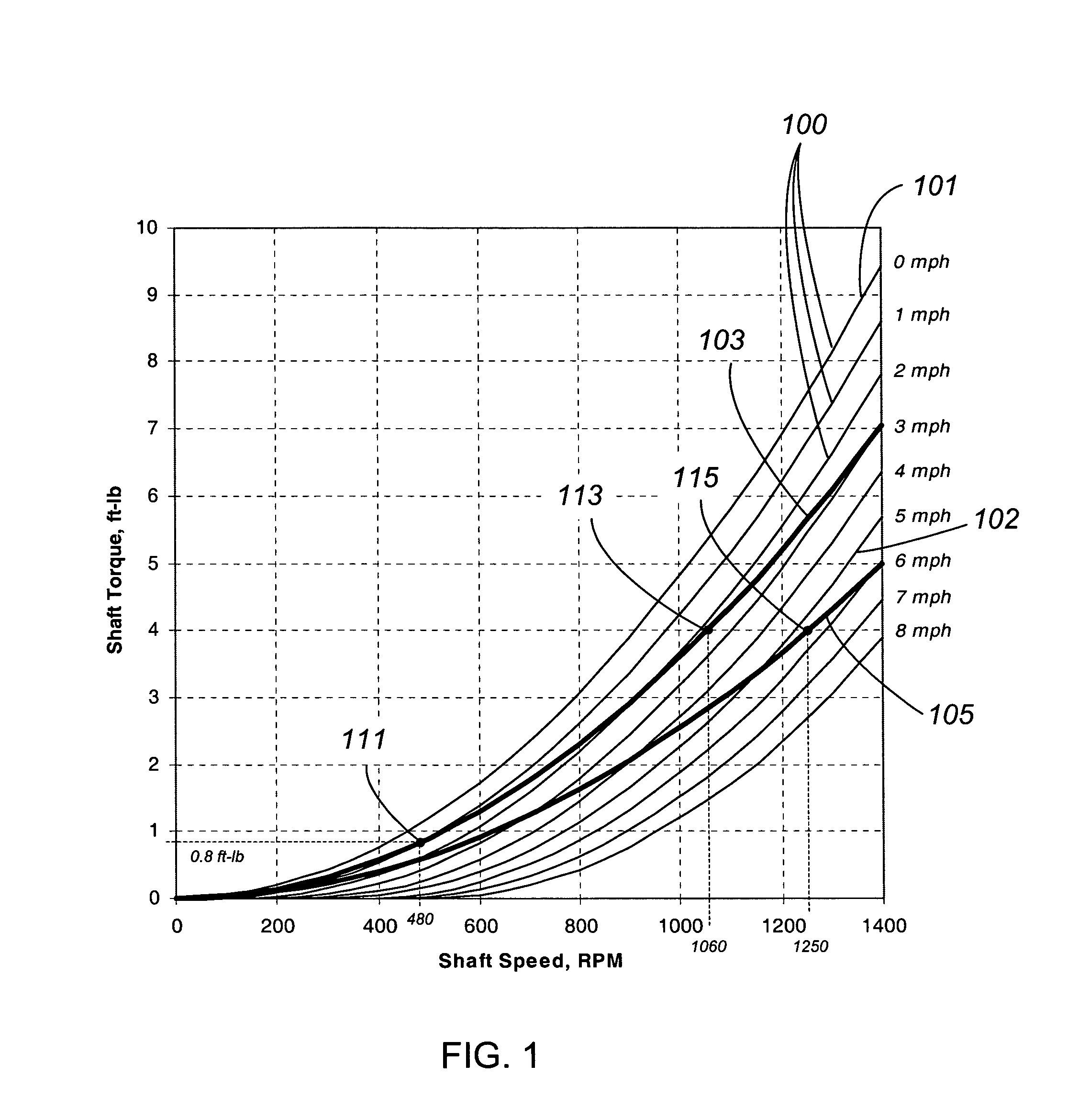
[0086]The example graph of FIG. 1 shows a sequence of thin solid lines 100 illustrating the relationship between propeller shaft speed and shaft torque for a particular propeller often used for trolling motor applications. These are the propeller characteristic curves. Each of the thin solid lines on the graph represents a constant watercraft speed relative to the water as labeled in increments of 1 mph (mile per hour). The 0 mph line 101 illustrates the shaft torque required to spin the propeller over a shaft speed range of 0 to 1400 RPM when the watercraft is stationary with respect to the water. Similarly, the 5 mph line 102 illustrates the shaft torque required to spin the propeller over a shaft speed range of 0 to 1400 RPM when the watercraft is traveling at a constant speed of 5 mph. It is important to note that the relationship between shaft torque, shaft speed, and watercraft speed illustrated by thin lines 100 are unique for each propeller design wi...
PUM
 Abstract
Description
Claims
Application Information
 - R&D
- Intellectual Property
- Life Sciences
- Materials
- Tech Scout
- Unparalleled Data Quality
- Higher Quality Content
- 60% Fewer Hallucinations
Browse by: Latest US Patents, China's latest patents, Technical Efficacy Thesaurus, Application Domain, Technology Topic, Popular Technical Reports.
© 2025 PatSnap. All rights reserved.Legal|Privacy policy|Modern Slavery Act Transparency Statement|Sitemap|About US| Contact US: help@patsnap.com


