
Fuel cell stack with passive air supply

a fuel cell and air supply technology, applied in the field of fuel cell stacks, can solve the problems of limited electrode area, battery life is finite, and system enhancement of pefcs portability,

Inactive Publication Date: 2006-01-17
LOS ALAMOS NATIONAL SECURITY
View PDF10 Cites 48 Cited by
  • Summary
  • Abstract
  • Description
  • Claims
  • Application Information

AI Technical Summary

Problems solved by technology

These systems did not enhance the portability of PEFCs.
However, batteries have a finite lifetime and cannot be recharged or regenerated in the field.
Because of these merits, the passive air power systems have potential as portable power sources of choice for both military and commercial markets, especially for low power applications, where the overall system specific energy density requirement, as high as a few thousands watts per kg, does not permit the added weight of complicated auxiliary equipment and control systems.
A drawback in the annular design is the limitation in the size of electrode area.
As the electrode area is increased, the portion of the peripheral area from which oxygen from air diffuses readily to the electrode becomes small and stack performance suffers.
The annular design provides greater energy than a conventional NiCad battery of similar size, but does not deliver power levels as high as NiCad batteries.

Method used


Image

  • Fuel cell stack with passive air supply
  • Fuel cell stack with passive air supply
  • Fuel cell stack with passive air supply

Examples


Embodiment Construction

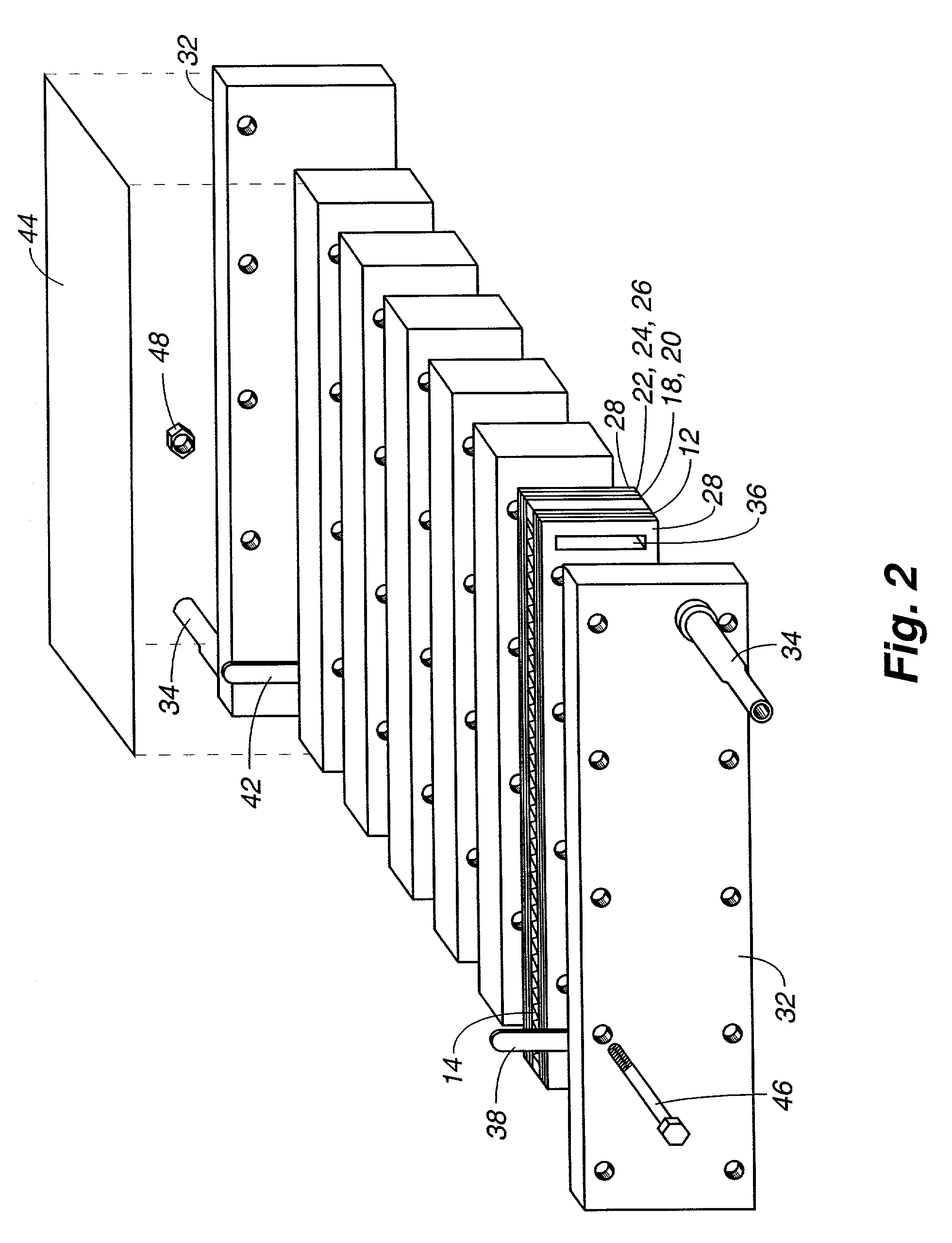
[0018]In accordance with the present invention, power density and energy conversion efficiency in a fuel cell stack having a passive air supply are increased by the use of (1) an elongated electrode geometry, which shortens the length for atmospheric air to reach the center of air cathode electrode, and (2) open air cathode flow field, which enhances reactant air and product water transport. In the stack described herein, an air cathode flow field, described in U.S. patent application Ser. No. 09 / 472,388, incorporated herein by reference, now abandoned, is combined with an elongated rectangular geometry of the electrode. The air cathode flow field is a perforated corrugated design that permits both axial and lateral movement of reactant along the flow field In a preferred embodiment, the anode flow field is also provided with a perforated corrugated design. A uniform distribution of reactant and reaction products is obtained to maximize use of the fuel cell active electrode area.

[00...


PUM


Abstract

A fuel cell stack has a plurality of polymer electrolyte fuel cells (PEFCs) where each PEFC includes a rectangular membrane electrode assembly (MEA) having a fuel flow field along a first axis and an air flow field along a second axis perpendicular to the first axis, where the fuel flow field is long relative to the air flow field. A cathode air flow field in each PEFC has air flow channels for air flow parallel to the second axis and that directly open to atmospheric air for air diffusion within the channels into contact with the MEA.

Description

RELATED APPLICATIONS[0001]This application claims the benefit of provisional patent application Ser. No. 60 / 315,827 filed Aug. 29, 2001.STATEMENT REGARDING FEDERAL RIGHTS[0002]This invention was made with government support under Contract No. W-7405-ENG-36 awarded by the U.S. Department of Energy. The government has certain rights in the invention.FIELD OF THE INVENTION[0003]The present invention relates generally to fuel cell stacks using hydrogen or methanol fuel, and, more particularly, to fuel cell stacks having a passive air supply.BACKGROUND OF THE INVENTION[0004]Polymer electrolyte fuel cells (PEFCs) have been developed for many applications, including low power applications that are now served by conventional batteries. PEFCs require a fuel supply, such as hydrogen or methanol, and an oxidant, which may be air. Early fuel cells required systems that provided fuel cell cooling and a pressurized and humidified air supply. These systems did not enhance the portability of PEFCs....

Claims


Application Information

Patent Timeline
IPC IPC(8): H01M2/14
CPCH01M8/04089H01M8/0254H01M8/026H01M8/0273Y02E60/50H01M8/04119H01M2008/1095
Inventor REN, XIAOMINGGOTTESFELD, SHIMSHON
Owner LOS ALAMOS NATIONAL SECURITY
Learn More