Backward wave coupler for sub-millimeter waves in a traveling wave tube

a traveling wave tube and backward wave technology, which is applied in the direction of parametric amplifiers, klystrons, klystrons, etc., can solve the problems of inefficient coupling between the slow wave structure and the output waveguide, inability to manufacture the device shown in fig. 3 for use in sub-millimeter wavelengths, and inefficient coupling of rf energy

Inactive Publication Date: 2006-01-17
CALABAZAS CREEK RES
View PDF12 Cites 20 Cited by
  • Summary
  • Abstract
  • Description
  • Claims
  • Application Information

AI Technical Summary

Benefits of technology

[0024]A slow wave structure for a backward wave traveling wave tube comprises a substrate having a plurality of pins, known as pintles. The pintles are elongate cantilever structures interacting with an electron beam traveling in a beam tunnel. The pintles have one end mounted to/and perpendicular to the substrate, and an opposing cantilever end. The pintles are small in comparison to the physical wavelength of the electromagnetic wave counter-propagating with the electron beam. The cantilever end of the pintles forms a substantially planar surface in the region of the electron beam, and the substrate supporting the pintles and located below the electron beam includes an exit aperture and at least one step change located a half wavelength from the exit aperture on the electron beam

Problems solved by technology

One of the problems with devices that operate in backward wave regions is the inefficiency of coupling between the slow wave structure and the output waveguide.
Fabrication of the device shown in FIG. 3 for use in sub-millimeter wavelengths is very difficult, as the features are on the order of 10s of microns, and the sloping sectio

Method used


Image

  • Backward wave coupler for sub-millimeter waves in a traveling wave tube
  • Backward wave coupler for sub-millimeter waves in a traveling wave tube
  • Backward wave coupler for sub-millimeter waves in a traveling wave tube

Examples


Embodiment Construction

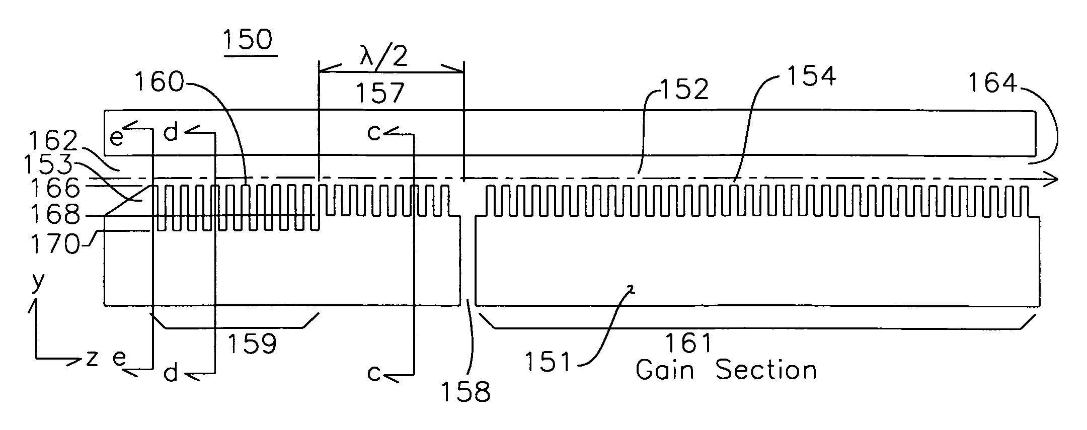
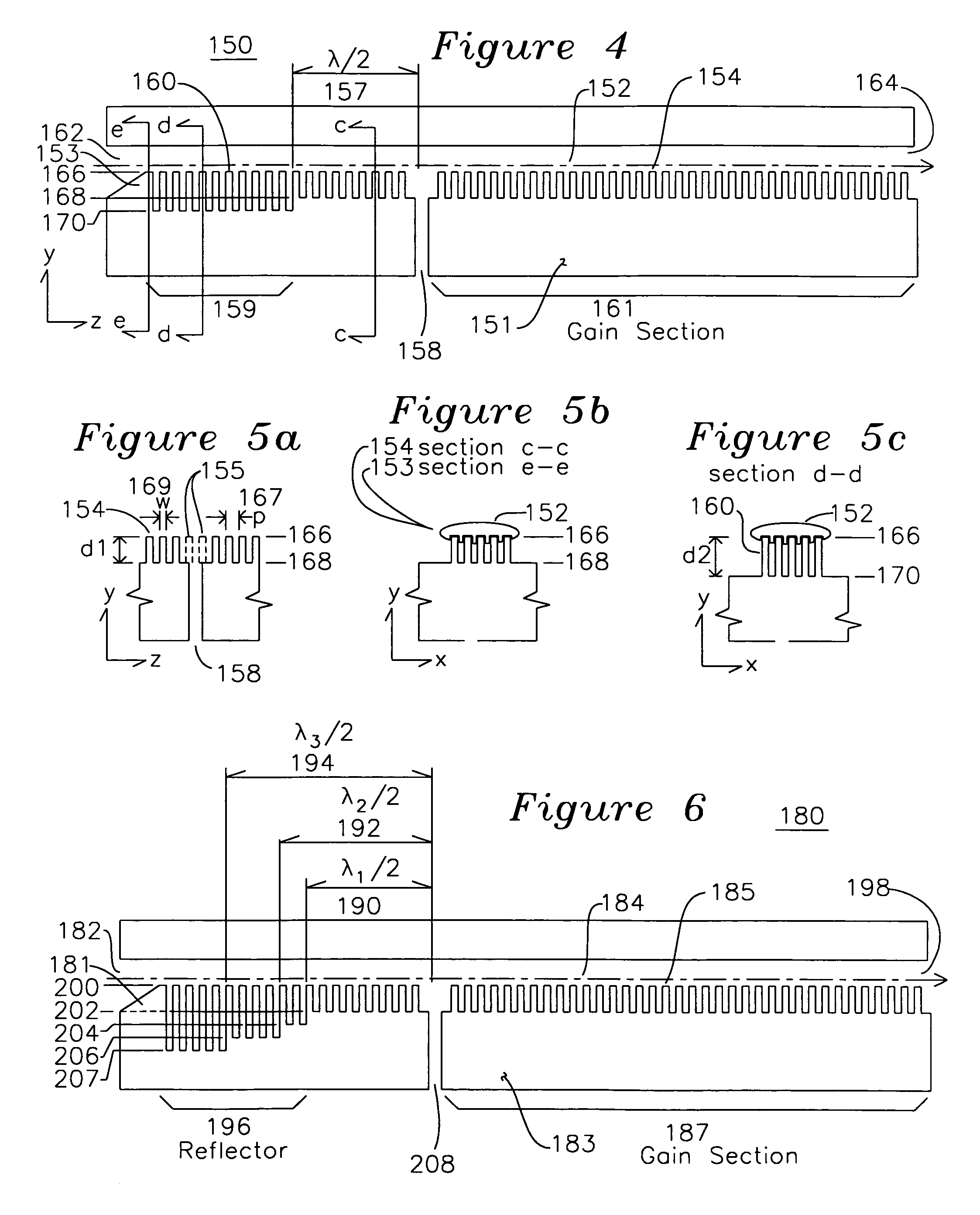
[0036]FIG. 4 shows the side view of a backward wave coupler 150 for a traveling wave tube, which is defined in a coordinate system y and z axis as shown, and an x axis (shown in FIGS. 5b and 5c) perpendicular to the y and z axis. An electron beam 152 is emitted from a cathode (not shown) and enters beam tunnel entrance 162, where it travels over beam shaper 153. This beam shaper 153 may have a plurality of slots parallel to the axis of electron beam 152 and over and around a plurality of pintles 154, which comprise corrugations having a pitch p, a width w, a depth d1 as shown in FIG. 5a, and may also include slots substantially aligned with the slots of beam shaper 153, and parallel to the axis of electron beam 152. The electron beam 152 may include counter-propagating RF at a wavelength λ, and the pintles 154 are spaced at less than 0.1λ in the z and optionally x directions. The pintle surface plane 166 is planar with a surface of the beam shaper 153 and a z-x plane below the elect...


PUM


Abstract

A slow wave structure for coupling RF energy with an electron beam comprises a co-propagating RF section including a plurality of pins having a uniform separation from the plane of an electron beam axis. An output aperture is positioned a half wavelength from a reflection section comprising a change in depth of the pintles, such that RF energy reflected by the change in pintle depth is added to the RF energy traveling with the electron beam. One or more rows of pintles are removed in the region of the output aperture to enhance coupling to the output aperture. The device may include a beam shaper for shaping the electron beam to surround the pintles, and the beam shaper and pintles may share common channels which are longitudinal to the electron beam axis. The slow wave structure may operate in forward and backward wave modes, and may be used in conjunction with other structures to form amplifiers and oscillators.

Description

[0001]This invention was made with United States government support under Grant NAS3-01014 from National Aeronautics and Space Administration. The United States Government has certain rights in this invention.FIELD OF THE INVENTION[0002]The present invention is related to coupling structures for microwave traveling wave tubes. More particularly, it is related to a structure for coupling traveling waves into and out of a traveling wave tube, including the class of traveling wave tubes operating in the sub-millimeter wavelength region.BACKGROUND OF THE INVENTION[0003]A Traveling-Wave Tube (TWT) may act as an amplifier or an oscillator for Radio Frequencies (RF). This is accomplished through the interaction of an electron beam and an RF circuit known as a slow wave structure, where the RF wave velocity as it travels down the circuit is much less than that of light in a vacuum. As the electron beam travels down this interaction region, an energy exchange takes place between the electron...

Claims


Application Information

Patent Timeline
IPC IPC(8): H01J25/34
CPCH01J25/40
Inventor CAPLAN, MALCOLMRADOVICH, DANILOKORY, CAROL L.
Owner CALABAZAS CREEK RES
Why Eureka
Try Eureka