

Camera having shake correction device mounted thereon
a technology of shake correction and camera, which is applied in the field of shake correction device mounted on, can solve the problems of time delay in shake prevention operation, image quality lowering, and complicated image processing operation
- Summary
- Abstract
- Description
- Claims
- Application Information
AI Technical Summary
Benefits of technology
Problems solved by technology
Method used
Image

Examples
first embodiment
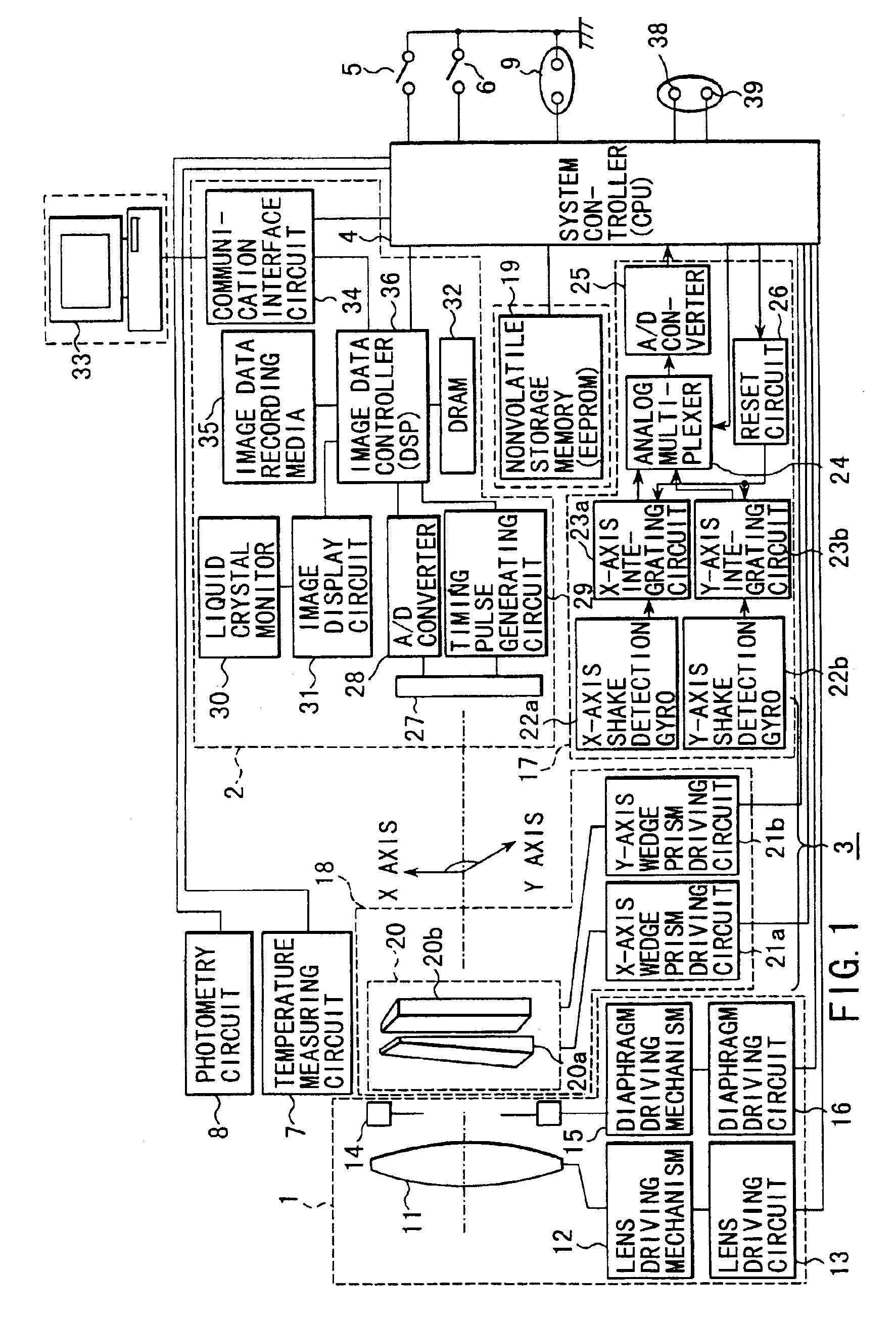
[0039]FIG. 1 shows an example of the schematic construction of an electronic still camera containing a shake correction device as this invention.
[0040]The camera roughly includes a photographing optical system 1, an image-sensing image processing section 2, a shake (or jiggle) correcting section 3, and a system controller (CPU) 4 for controlling the above constituents and the whole portion of the camera and further includes a power switch 5, a release switch 6, a temperature measuring circuit 7 for measuring the temperature of the camera, a photometry circuit 8 for measuring the luminance of a subject, and a test terminal 9 and the like which will be described later. The opening of a diaphragm 14 which will be described later and the shutter period (integrated time) of an image sensing device are determined based on luminance information obtained by the photometry circuit 8.
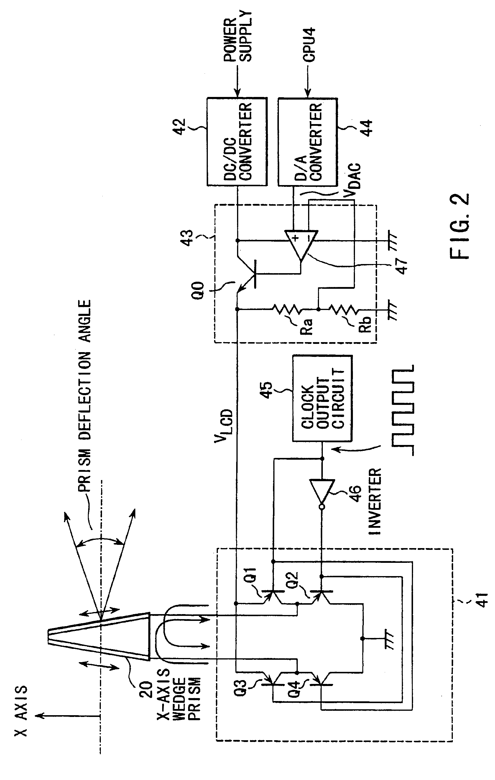
[0041]Since the characteristic of the index of refraction of the wedge prism varies with a change in the ambie...
second embodiment
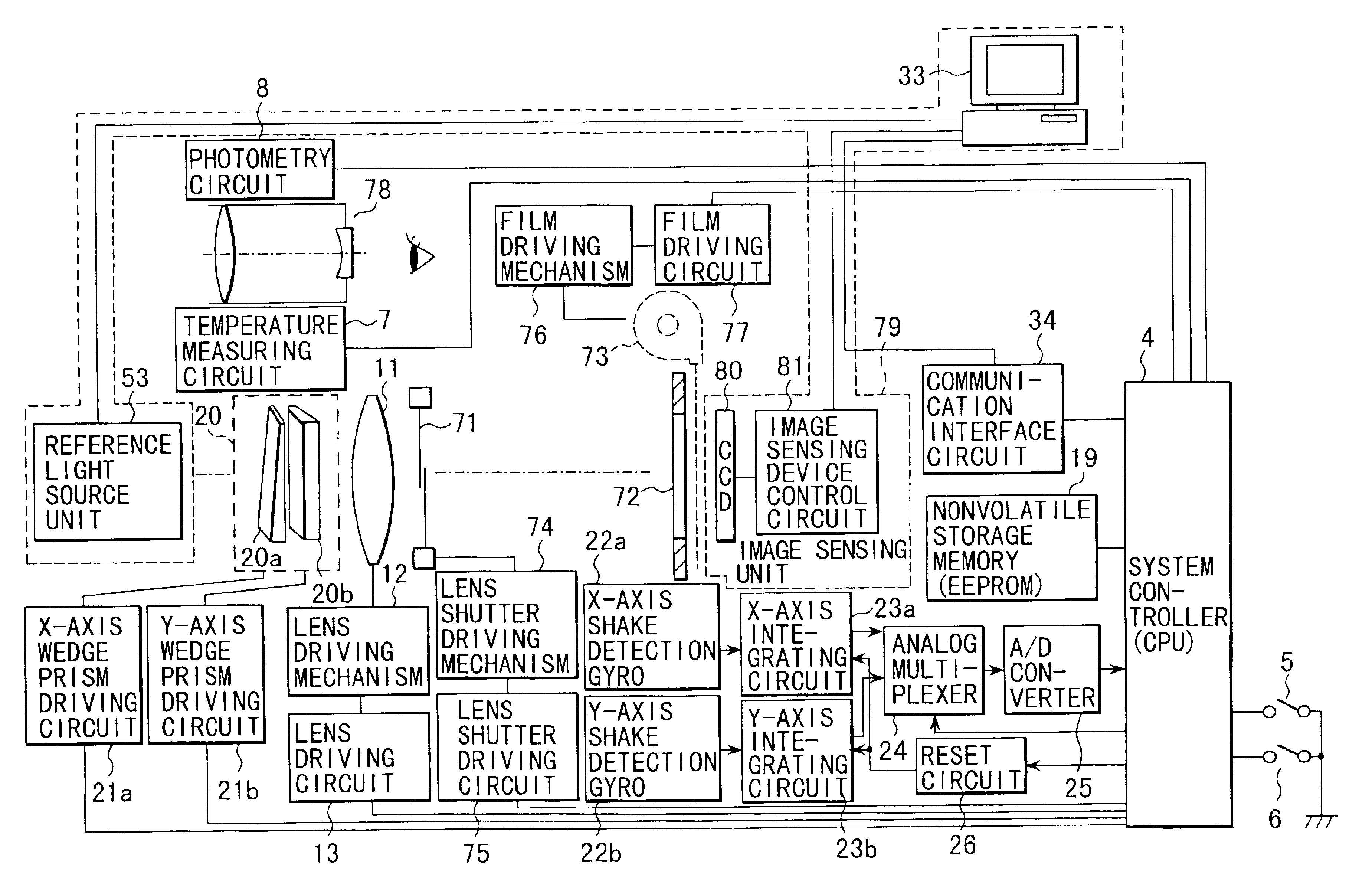
[0119]FIG. 10 shows an example of the schematic construction of a silver halide film camera containing a shake correction device according to this invention.
[0120]Portions shown in FIG. 10 which are the same as those of the first embodiment shown in FIG. 1 are denoted by the same reference numerals and the explanation therefor is omitted.
[0121]The camera of this embodiment includes an optical finder 78 and a photographing lens 11, lens shutter 71 and aperture 72 are disposed behind a wedge prism 20. A film 73 is loaded into the camera via the aperture 72.
[0122]The lens shutter 71 is used instead of the diaphragm 14 of the first embodiment and a sector provided on the lens shutter 71 is driven by a lens shutter driving mechanism 74 having an actuator. Power required for driving the actuator is supplied from a lens shutter driving circuit 75 controlled by a CPU 4. Therefore, the lens shutter driving circuit 75 can be controlled by the CPU 4 so that the film 73 can be exposed for a tim...
PUM
 Abstract
Description
Claims
Application Information